R Commercial Service / Training Manual High Speed Combination Oven ACE / MCE - 60 Hz October 2012 16400018 ®/ ™ © 2012 Amana. All rights reserved. Brand used under license..
Table of Contents Important Safety Information.........................................................................................1-5 Installation.......................................................................................................................7 !"#$%#&'$()*++++++++++++++++++++++++++++++++++++++++++++++++++++++++++++++++++++++++++++++++++++++++++++++++++++++++++++++++++, Quick Start Reference Guide ACE14 / MCE14..........................................................9-17 -.
1 Important Safety Information 1
Important Information Important Notices for Servicers and Consumers ACP will not be responsible for personal injury or property damage from improper service procedures. Pride and workmanship go into every product to provide our customers with quality products. It is possible, however, that during its lifetime a product may require service.
Important Safety Information ! WARNING Read the following information to avoid possible exposure to microwave radiation: The basic design of the Microwave Oven makes it an inherently safe device to both use and service. However, there are some precautions which should be followed when servicing the microwave to maintain this safety. These are as follows: 1. Always operate the unit from an adequately grounded outlet. Do not operate on a two-wire extension cord. 8.
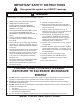
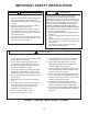
IMPORTANT SAFETY INSTRUCTIONS Recognize this symbol as a SAFETY message ! WARNING When using electrical equipment, basic safety precautions should be followed to reduce the risk of burns, "D"#'1$#&D/*G(#K^/%1"^/(1/$)M21E/'(/!"1*()*/$)#D2@$)?/'G"/<(DD(_$)?+/ 1. READ all instructions before using equipment. `+/ C-/Q->/G"&'/J&JE/J(''D"*/$)/(.")+ :+/ P43C/3QC/R-SS-F/'G"/*!"#$%#/ T;P403U>V-Q />-/3W-VC/;- VXS4/ 4Y;- UP4/>-/4Y04 VW4/8V0P-F3W4/ 4Q4PZ[\/()/'G$*/!&?"+ 10.
IMPORTANT SAFETY INSTRUCTIONS WARNING WARNING >(/&.($@/1$*K/(
2 ACE14 / MCE14 60 Hz Specifications Installation · Unpacking the oven · Oven Clearances Power Specification · Input · Output · Consumption Dimensions · Weight 6
Installation STEP 1 - Unpack Oven e e/ e/ e/ Inspect oven for damage such as dents in door or inside oven cavity. P"!(1'/&)E/@")'*/(1/J1"&K&?"/'(/*(21#"/(
73(!&8!1)&",5 9:;<= > ?:;<= Models ACE14* / MCE14* Power Source Voltage AC Amperage (Single Unit) Frequency Single Phase, 3 wire grounded Receptacle Plug Power Output Microwave Nominal microwave energy (IEC705) Minimum temperature rise ( T) Operating Frequency Power Consumption Microwave only Convection only Combination Dimensions Cabinet (in / cm) Width Height Depth Oven Interior (in / cm) Width Height Depth Weight Crated Uncrated EZ Card Menu Management 230 VAC 20 A 60 Hz X 6-20R 6-20P 1400 Watts 10ºF
3 ACE14 / MCE14 60 Hz Quick Start Reference Guide 9
!"#$%&%'!"#$ Display and Features A—Oven Door Handle (Lift to open.) B—Rack Guides C—Top Control Panel D—Display E—Side Control Panel G—Air Intake Filter (some models) H —EZ Card Slot ? Oven Features Standby shows in display after oven door has been opened and !"#$%&'"(')*+$('+,(-.-/'"0$-'122' with the Preheat On/Off pad.
!"#$%&%'!"#$ Display and Features (cont’d) Ready and set temperature displays after pressing Preheat On/Off pad. Ready indicates the oven is up to temperature. 5$6)73!$'"*'89:;2'#<"=-> Indicates oven is in a preprogrammed cooking program Cooking information shows in display after pressing a single (or double) digit pad while in Ready Mode.
!"#$%&%'!"#$ Display and Features (cont’d) HIDDEN PAD POWER LEVEL TIME ENTRY PROGRAM SAVE HIDDEN PAD ()&(** STAGE TEMP ENTRY Cooking Display Start pad The Start pad is used to begin a manual time entry cooking cycle. DISPLAYS DESCRIPTION OVEN PREHEATING 450°F Stop/Reset pad The Stop/Reset pad stops a cooking sequence in progress, clears out any remaining time, and also ends a programming or user option cycle.
!"#$%&%'!"#$ Programming Programming Pads Oven is shipped from the factory for single pad programming. To change the oven default to double pad programming, see User Option section. To program the amount of time, power level, or temperature setting for a pad: F4' 10$-'7,#+'E$'1U4 @' M($##'M($<$)+'1-V1**'3)%4 @' Oven Preheating 450°F shows in display with Oven Preheating'C)#<.-/4'5$6)73!$'"*'89:;2'#<"=-> J4' 10$-'($) <$#'3($<$)+'+$73$()+,($4 @' R.
!"#$%&%'!"#$ Convection Cooking ! CAUTION To avoid risk of burns, handle utensils, racks, and door with care. Allow oven, utensils, and racks to cool before cleaning. Oven, utensils, and racks, become hot during operation. To operate the oven for convection cooking only, you can use preprogrammed pads or manual time entry. The 21AA186/>%6/0,.-7,61/0%9.4%21.%71/:47,61/%711=6/>%1/A@B'2"(' "7E.-)+."-' ""D.-/&'#$$'+<)+'#$ +.
!"#$%&%'!"#$ Combination Cooking (microwave and convection) ! CAUTION To avoid risk of burns, handle utensils, racks, and door with care. Allow oven, utensils, and racks to cool before cleaning. Oven, utensils, and racks, become hot during operation. To operate the oven for combination cooking, you can use preprogrammed pads or manual time entry. The 21AA186/>%6/0,.-7,61/0%9.4%21.%715?6/9,61/%711=6/>%1/A@B'2"(' "-0$ +."-'"-!P' ""D.-/&'#$$'+<)+'#$ +."-4 Combination Cooking With Preprogrammed Pads 1.
!"#$%&%'!"#$ User Options HIDDEN PAD POWER LEVEL TIME ENTRY PROGRAM SAVE HIDDEN PAD :0;:<< TEMP ENTRY STAGE Changing user options Options such as single or double pad programming, beep volume, and maximum cooking time can be changed to suit individual preferences. Didn’t like an option? Factory settings are marked in bold. To change the oven back to the factory setting, simply select the option that is marked in bold. My changes weren’t saved.
/=>?@";"A=>?@ EZCard Operating Instructions (some models) PROGRAM SAVE Update programs in seconds! EZCard slot To program the oven using the EZCard: :-(&"45,*"B("+&".*%&6B8"4!6("CDE($(%*"45,*"B(":<,*0%/#-!+,;5#$6 ! ?1,!CNB#*$!/#(!:,!%(&,*0,$!2.*9#*$&!.*!:#/+9#*$&6 NOTE: If 00:00!$%&5-#;&D!A!:,,5&! A6! 35,(!#($!/-.&,!$..*6 sound and the display returns to the F6! "*,&&!#($!1.
4 ACE14 / MCE14 60 Hz Oven Construction 18
! WARNING To avoid risk of electrical shock, personal injury or death; disconnect power to oven and discharge capacitors before following any disassembly procedures. Component Location RTD Touch Panel (Top) Triac #1 Motors A (front) Touch Panel (Side) Plug Triac #2 Heating Element B (rear) Data Key Board Triac #3 Microwave Figure 1 Touch Panels/Displays/Triacs Fan Blade High Voltage Components Magnetron Fuse Block Capacitor Fuse H.V. Board Filter Interlock Switch Assembly Figure 2 H.V.
:-(&"=!&,*E5#*+!& ! WARNING To avoid risk of electrical shock, personal injury or death; disconnect power to oven and discharge capacitors before following any disassembly procedures.
!"#$%&#'()*+(,&# ! WARNING To avoid risk of electrical shock, personal injury or death; disconnect power to oven and discharge capacitors before following any disassembly procedures.
!"#$-").&)/0#+"$1"'( All Amana and Menumaster microwave oven power outputs are rated using the IEC705 standards. Using the IEC705 test method requires precision measurements and equipment that is not practical to be performed in the field. Using the test shown below will indicate if the oven performance is satisfactory. Test equipment required: 1000 ml test container and thermometer (ACP Power Test Bpwl part # 12018801).
7 ACE14 / MCE14 60 Hz Component Testing Procedures 23
Component Testing Procedures ! WARNING To avoid risk of electrical shock, personal injury or death; disconnect power to oven and discharge capacitors before following any disassembly procedures. Illustration Component Thermal cutout 31866P01 ............... Test Disconnect all wires from TCO. Measure resistance across terminals. Control TCO . ............................................ B5684121............... Magnetron TCO....................................... .
Component Testing Procedures ! WARNING To avoid risk of electrical shock, personal injury or death; disconnect power to oven and discharge capacitor before servicing, unless testing requires power.
Component Testing Procedures ! WARNING To avoid risk of electrical shock, personal injury or death; disconnect power to oven and discharge capacitor before servicing, unless testing requires power. Illustration Test Continuity is indicated as 100 below. Top touch panel Continuity is indicated as 100 below. High voltage board to display module harness Test continuity of wires.
Component Testing Procedures ! WARNING To avoid risk of electrical shock, personal injury or death; disconnect power to oven and discharge capacitor before servicing, unless testing requires power. H.V. board Function Test Set-Up Input to H.V. board At H.V.
8 ACE14 / MCE14 60 Hz Service Test 28
!"#$%!&'!()&*+,-.&/&0+,-. Accessing Service Mode (Turn Oven Off) Service Mode Pressing Hidden Pad, 1, 3, 5, 7, 9 while in Preheat is OFF Main Service Mode Menu Mode Name Entry Functional Description Display S 6 e 0 r v H i Z c e 2 M o 0 8 d e V Pad 1 Service Pad 1 Pressing Pad 1 while in Service Mode Calrod #1 and convection fan shall be toggled. When on, it shall run for 62 seconds.
!"#$%!&'!()&*+,-.&/&0+,-. Pad 4 Service Pad 4 Pressing Pad 4 while in Service Mode Convection Fan shall be toggled. Mode Name Entry Functional Description Display C o n v . A F a m p n s : : O 0 N 3 O N Pad 5 Service Pad 5 Pressing Pad 5 while in Service Mode Auxiliary Output shall be toggled. Mode Name Entry Functional Description Display A u x .
!"#$%!&'!()&*+,-.&/&0+,-. Pad 8 Service Pad 8 Pressing Pad 8 while in Service Mode Displays Door Cycles stored in EEPROM. Will always be a multiple of ten. Mode Name Entry Functional Description Display D o o 0 r 0 2 C 4 y 5 c 3 l 8 e 0 s Pad 9 Service Pad 9 Pressing Pad 9 while in Service Mode Prompts user to clear service information. Mode Name Entry Functional Description Display P C r l e e s a s r S s T e A r R v T .
TEST MODES ! WARNING To avoid risk of electrical shock, personal injury or death; disconnect power to oven and discharge capacitors before following any disassembly procedures. Convection Temperature Test Convection Temperature Calibration NOTE: It is absolutely necessary to own and use a thermocouple type oven tester to accurately measure oven temperatur e. No other type of thermometer can take its place.
DISPLAY DIAGNOSTICS Error Codes: During operation, the display may show the following service codes: Note: Before scheduling service for any error codes, instruct customer to unplug oven for 1 minute, reconnect power, and re-test. If unit operates properly, no service call is required. DISPLAY DESCRIPTION CORRECTIVE ACTION Error 1U Chassis Memory Not Found Error 1F Error 2 Chassis Memory Not Programmed Failed H.V.
9 ACE14 / MCE14 60 Hz Wiring Diagrams / Schematics 34
!"!#$%&!'$"'(%)'(*+,%-./01%2%3.
)45,('6!4%)'(*+,%-./01%2%3.
!"#$ 37
+12"( !/(':9&&&';( +25-"#0(5-('% 7778'4*9:+;6!:#984:( %&'%()*+(,-.