Service Instructions Package Terminal AirConditioners & Heat Pumps This manual is to be used by qualified, professionally trained HVAC technicians only. Goodman does not assume any responsibility for property damage or personal injury due to improper service procedures or services performed by an unqualified person. ® RS4200003 Rev. 5 April 2009 is a registered trademark of Maytag Corporation or its related companies and is used under license to Goodman Company, L.P., Houston, TX. All rights reserved.
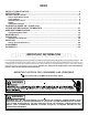
INDEX PRODUCT IDENTIFICATION ........................................................................................................ 4 SPECIFICATIONS ......................................................................................................................... 6 PROPER INSTALLATION ........................................................................................................... 17 WALL SLEEVE INSTALLATION .................................................................................
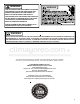
WARNING WARNING THIS AIR CONDITIONER IS NOT MEANT TO PROVIDE UNATTENDED COOLING OR LIFE SUPPORT FOR PERSONS OR ANIMALS WHO ARE UNABLE TO REACT TO THE FAILURE OF THIS PRODUCT. THE FAILURE OF AN UNATTENDED AIR CONDITIONER MAY RESULT IN EXTREME HEAT IN THE CONDITIONED SPACE CAUSING OVERHEATING OR DEATH OF PERSONS OR ANIMALS. PRECAUTIONS MUST BE TAKEN TO WARN OF OR GUARD AGAINST SUCH AN OCCURENCE.
PRODUCT IDENTIFICATION PT C 07 3 B 35 A BASIC MODEL TYPE PT = Standard PTAC GM = Goodman PTAC DRY = Dehumid PTAC M BM MAJOR/MINOR DESIGN REV. REFRIGERATION CYCLE C = Cooler Only H = Heat Pump COOLING CAPACITY 07 = 7000 BTUH 09 = 9000 BTUH 10 = 10000 BTUH 12 = 12000 BTUH 15 = 15000 BTUH RATED VOLTAGE 2 = 115V 60Hz 1Ph 3 = 230/208V 60Hz 1Ph 4 = 265V 60Hz 1Ph 5 = 240/220V 50Hz 1Ph DESIGN STYLE Old MAJOR DESIGN SERIES A = 3/8" Slab Cond.
PRODUCT IDENTIFICATION NT E 12 A 35 A 3 A Package Engineering Terminal Units Revision Model Type E - Cooler P - Heat Pump Voltage 3 = 230/208-1-60 4 = 265-1-60 Option Code Nominal Cooling Capacity 07: 7,000 Btuh 09: 9,000 Btuh 12: 12,000 Btuh 15: 15,000 Btuh A = Standard Model C = Seacoast Model Electric Heat 25 = 2.
SPECIFICATIONS COOLING DATA (COOLING with ELECTRIC HEAT) PTC073A**AA Voltage 1&3 Capacity (BUTH) PTC074A**AA PTC093A**AA PTC094A**AA PTC123A**AA PTC124A**AA PTC153A**AA PTC154A**AA 230/208 265 230/208 265 230/208 265 230/208 265 7,500/7,400 7,500 9,000/8,800 9,000 12,200/12,000 12,200 14,200/14,000 14,200 Amps 2.5/2.6 2.0 3.5/3.8 3.0 4.6/5.0 3.7 7.4/7.9 6.5 Watts 625/610 625 810/790 810 1,145/1,125 1,145 1,510/1,490 1,510 11.6 11.6 11.1 11.1 10.8 10.8 9.
SPECIFICATIONS HEATING PERFORMANCE - REVERSE CYCLE Heating Capacity PTH073A**AA 1&7 Reverse Cycle PTH074A**AA PTH094A**AA PTH123A**AA PTH124A**AA PTH153**AA PTH154A**AA Amps 2.6/3.0 2.2 2.6 4.5/5.1 3.9 5.0/5.6 4.1 Wa tts 575/56 5 575 7 70 1,020/1,000 1,020 1 ,350/1,320 1,350 6,800/6,700 6,800 8,500 11,200/11,100 11,200 13 ,400/13,100 13,400 COP 3.3 3.3 3.2 3.1 3.1 2.9 2.
SPECIFICATIONS HEATING PERFORMANCE - REVERSE CYCLE Heating Capacity Reverse Cycle 1& 7 P TH073A**AB P TH073A**AC PTH074A**AB PTH074A**AC PTH093A**AB PTH093A**AC PTH094A**AB PTH094A**AC PTH123A**AB PTH123A**AC PTH124A**AB PTH124A**AC PTH153A**AB PTH153A**AC PTH154 A**AB PTH154 A**AC Amps 2.6/3.0 2.2 3.2/3.6 2.6 4.5/5 .1 3.9 5.7/6.3 5.
SPECIFICATIONS COOLING DATA (COOLING with ELECTRIC HEAT) PTC073B*** E- Y V oltage 1&3 Capacity (BUTH) P TC074B*** E- Y PTC0 93B*** E- Y PTC09 4B*** E-Y PTC1 23B*** E- Y PTC124B*** E-Y P TC153B*** E- Y PTC154B*** E- Y 230/208 265 230/208 265 230 /208 265 2 30/208 265 7,100/6,900 7,100 9,100/8,900 9,100 12,000 /11,900 12 ,000 14,0 00/13,900 14,000 Amps 2.8/3.0 2 3.7/3.8 3 4.6 /5.0 4.3 6.3/6.9 5.
SPECIFICATIONS HEATING PERFORMANCE - REVERSE CYCLE Heating Capacity 1& 7 Reverse Cycle 12 PTH073B*** E-Y PTH074B*** E -Y PTH093B*** E -Y PTH094B*** E -Y PTH123B*** E -Y PTH124B*** E -Y PTH153B*** E -Y PTH154B*** E-Y 1 3,300 6,200/6,00 6200 8,200/8,000 8200 10,800/1 0,600 10800 13,300/13,200 Watts 2.6/3.0 2.2 3.2/3.6 2.6 4.5/5 .1 3.9 5.7/6.3 5.4 BTUH5 550/530 550 750/73 0 750 102 0/1,000 1020 1,340/1,330 1,340 Amps 5 3.3 3.3 3.2 3.2 3.1 3.1 2.9 2.
SPECIFICATIONS COOLING DATA (ELECTRIC HEAT) NTE07A**A3A Voltage 1&3 Capacity (BUTH) NTE07A**A4A NTE09A**A3A NTE09A**A4A NTE12A**A3A NTE12A**A4A NTE15A**A3A NTE15A**A4A 230/208 265 230/208 265 230/208 265 230/208 265 7,100/6,900 7,100 9,100/8,900 9,100 11,900/11,700 11,900 13,700/13,500 13,700 Amps 2.8/3.0 2.3 3.7/3.8 3.0 4.9/5.3 4.3 6.3/6.9 5.9 Watts 655/640 655 830/810 830 1,165/1,145 1,165 1,540/1,515 1,540 10.8 10.8 11 11 10.2 10.2 8.9 8.9 4.0 3.6 5.
SPECIFICATIONS PTC****A* COOLING DATA (COOLING with ELECTRIC HEAT) PTC 073D**AR PTC 093D**AR PTC 123C**AM PTC 123D**AR PTC 133D**AR PTC 153D**AR 230 / 208 230 / 208 230 / 208 230 / 208 230 / 208 230 / 208 7,200/7,000 9,100 / 8,900 3.5/3.5 4.4/4.4 4.8/5.2 5.4/5.4 5.9/6.4 6.7/6.7 Watts 625/600 790 / 775 1,070,/,1,040 1,120,/,1,100 1265/1235 1445/1420 EER 11.5/11.7 11.5 11.0/11.2 10.7 10.5/10.7 9.7 4.2 5.4 6.4 6.6 7.8 8.
PTH********[M/R/Z] SPECIFICATIONS COOLING DATA (HEAT PUMP) Model PTH 073D***[R/Z] 1, 7 , 9 , 10 , 12 Voltage 1 , 3, 1 2 Capacity (BUTH) Amps Watts EER UNIT WITHOUT ELECTRIC HEATER 2 , 4 , 12 Minimum Circuit Ampacity PTH 093D**AR PTH 123C**AM PTH 123D**AR PTH 094D**** PTH 124C**AM 230 / 208 230 / 208 230 / 208 230 / 208 265 230 / 208 7,000/6,800 9,000/8,800 11,500/11,200 11,700/11,500 9,100 11,300 3.5/3.5 4.4/4.4 4.8/5.2 5.4/5.4 3.6 4.
PTH********[M/R/Z] SPECIFICATIONS HEATING PERFORMANCE - REVERSE CYCLE Heating Capacity Reverse Cycle 1 Amps 12 PTH 123D**AR PTH 094D**** PTH 124C**AM 3.5/3.5 4.4/4.4 4.8/5.2 5.4/5.4 3.6 4.7 550/530 760/740 1,010/960 1,035/1,015 750 1,010 6,200/6,000 8,300/8,100 10,000/9,500 10,600/10,400 8,200 10,000 M Models 3.2/3.3 3.2 2.9 3.0 3.2 2.
SPECIFICATIONS OPERATING VOLTAGES WARNING USE EXTREME CAUTION WHEN CHECKING HIGH VOLTAGE. Use a voltmeter, check the voltage at the outlet. The reading must be within the minimums and maximums shown below for the operating voltage. Operating Voltages Operating Voltage Minimum Voltage Maximum Voltage 230/208 197 253 265 238 291 NOTE: 1. All 265 volt models must use subbase or hard wire kit. 2. Minimum branch circuit ampacity ratings conform to the National Electric Code.
PROPER INSTALLATION WALL SLEEVE INSTALLATION • If installed in a concrete or masonry wall, a lintel must be provided in the wall opening for support. Do not use the wall sleeve as a lintel. See Framing with Lintel Figure for a typical lintel construction. The wall sleeve must be installed before the air conditioner or heat pump chassis can be set in place. Read the instructions thoroughly before proceeding.
PROPER INSTALLATION 16 1/4" 415 mm Minimum 4 10 2 1/ Mi 75 m 4" n im m um Dimension "B" in Table 1 Minimum Interior and Exterior Projections Minimum Wall Opening Dimensions MINIMUM CLEARANCES AND PROJECTIONS Minimum Clearances Option A Minimum Projection B C in. mm in. mm in.
PROPER INSTALLATION Expansion Anchor Bolt Plastic Anchor Wall Receptacle Within 58" From Bottom Right Side Corner on 208/230 VAC Units Only Attaching Wall Sleeve to Opening Wall Sleeve Dimensions 6. Check the level of the wall sleeve and adjust if necessary. Outside Enclosure Panel Removal 7. Caulk or seal around the outside of the entire sleeve. The sleeve stiffener must be taken out before the enclosure panel can be removed from the sleeve. 8.
PROPER INSTALLATION 3. Lift the cabinet front off the chassis. Reverse this procedure to reinstall the cabinet front. CHASSIS INSTALLATION 1. Remove the cabinet front from the chassis as described in Front Removal. Front Mounting Holes - Two mounting holes are provided to give the owner the option of securing the front to the chassis. The mounting holes are located behind the intake grille. The owner must supply two 1/2 inch long #8 sheet metal screws per unit.
PROPER INSTALLATION POWER CORD REQUIREMENTS 230/208 Volt Units 265 Volt Units Power Cord Rating (amp) Power Cord Rating (amp) 1.5 15 20 2.5 15 20 3.5 20 Not Applicable 3.7 Not Applicable 20 5 30 30 Heater Size (kW) NOTE: Heaterless units are shipped with an auxiliary data label on the front side of the mid-partition panel. If an electric heater kit is field installed, the installer must mark the appropriate box on the label to indicate the electric heater capacity.
PROPER INSTALLATION X1 B Y Y/W1 W1 W2 W2 R C 14 Pin Connector Control Board Connections EH LS Thermostat Connections Thermostat Connections Y/W1 W1 W2 W2 Control Board Connections 18 Pin Connector Control Board Connections Thermostat Connections B Y R* Thermostat Connections 18 Pin Connector EH LS 14 Pin Connector Control Board Connections 21
PROPER INSTALLATION REMOTE/STANDARD SWITCH (NOT USED ON NTE OR NTP MODELS) The remote/standard switch is used to change the control of the unit from the standard on board controls in the standard mode, to a remote wall mounted thermostat in the remote mode. For remote control operation refer to Remote Operation section. To set remote switch on the "G & K" board, see Configuration Settings. ON/OFF W2 Y\W1 Front Desk Switch Fan Cycle Switch The fan cycle switch sets the operational mode of the fan.
PROPER INSTALLATION 71° F 68° F Indoor Ambient Thermistor 66° F 63° F 75° F 64° F 69° F 82° F 87° F 76° F 63° F Plastic Holder Indoor Coil 79° F 83° F Low End Cooling Limits High End Heating Limits 2. Cut off end of thermistor, separate leads 1” back from cut and strip 1/2” of insulation from each lead. 3. Wire nut the stripped leads to the two sensor wires running from terminals 2 and 3 on the remote temperature sensor base .
PROPER INSTALLATION Diagnostic Light Temperature Limiting Screws Temperature Limiter The green diagnostic light located in the lower left hand corner of the touchpad and indicates operation warnings. This light usually indicates that either the filter or coils need cleaning. Please refer to the Maintenance and Cleaning section for the proper cleaning procedure. If this light is still on after cleaning, please refer to the Diagnostic & Status Report section for assistance. Additional Control Inputs 4.
PROPER INSTALLATION Use the following procedure to change the angle of the discharge air flow: Label Vent Control Lever 1. Remove the front cabinet (see Front Removal). 2. Position the front so that the backside is accessible. Vent Control Vent Door Shipping Screw Rotate the vent control lever to either open or close the damper. 3. Remove the four nuts which secure the discharge air grille to the cabinet front.
PROPER INSTALLATION 2. To select a configuration feature code other than C1, key until the desired configuration press the HEAT comes up. To scroll to a previously viewed configuration codes press the COOL key. 3. Remove cabinet front from chassis by tilting the bottom of the front forward, lifting slightly up and forward.
PROPER INSTALLATION MOUNTING SENSOR/DOOR MAGNET INSTALLATION FOR DD01A KIT A DT01* must be installed in the PTAC unit for the DD01* to be operable. DOOR MAGNET INSTALLATION Mount the door magnet holder on the front of the door where it will be as close as possible to the bottom of the motion sensor but no more then 1/8" from the bottom center of the motion sensor (DD01*) when the door is closed. Skip these steps if not installing. 1. Remove motion sensor from mounting plate by pulling apart. 2.
PROPER INSTALLATION MAGNET SLOTS POSITION B Place magnet in Position B in instances when the door and frame align. DOOR TRIM MAGNET HOLDER TOP VIEW INSTALL THE MAGNET IN THE CORRECT SLOT. Select one of the three slots that places the magnet ½” from the sensor mounting plate on the door frame. See following examples. The door frame and door usually will not align.
PROPER INSTALLATION 3. Press and then immediately release the white tactile button on the back of the DD01* motion sensor. or should now be displayed on the PTAC LED display. DD01* If or does not show on the display in 1-2 seconds, then press and release the white button a second time. NOTE: If both a DD01* and a DS01* are being bound, then the display will show . Skip if there is no motion sensor. ot ½” SENSOR MOUNTING PLATE 4. Press “OFF” on the PTAC touchpad to exit the binding sequence. 5.
PROPER INSTALLATION ENTERING ROOM NUMBER (SKIP IF NOT USING DP01A FRONT DESK PLATFORM) W A R N IN G 1. The PTAC control can be set for a 4-digit room number. To select the first two digits (floor), press the HEAT key until appears, then press the up arrows to select the first two digits. down 2. To select the last two digits of the room number, press key until the HEAT up and down room number.
PROPER INSTALLATION 8. Press HEAT key to scroll to third unoccupied setback temperature. Press either the up or down arrow to the desired third unoccupied setback temperature. 9. Press HEAT key to scroll to third unoccupied setback time. Press either the up or down arrow to the desired third unoccupied setback time. 10.. To exit configuration mode: Press the OFF key. NOTE: Configuration feature mode will also automatically exit if no keys are pressed for a period of two (2) minutes.
PROPER INSTALLATION Feature Code --C1 C2 C3 Description Interface Usage Fan Operation Reverse Cycle Operation Room Identification first two digits C5 C6 Room Identification last two digits Wired Occupancy Wired Motion Sensor Type 0* rE L5 Unit is only controlled by the PTAC touchpad. Au* The fan only runs with the call for heating or cooling. On The fan runs continuously except in the OFF position. C bP The fan runs continuously in cooling and cycles with call for heating.
MAINTENANCE NOTE: The compressor does not require maintenance. It is hermetically sealed, permanently lubricated. The following procedure is used to remove the intake filter: 1. Open the intake grille by grasping the top intake louver. 2. Pull the intake grille open. WARNING 3. Slide filter upward and remove. 4. Clean filter with vacuum or with running water. Reverse this procedure to reinstall the filter.
MAINTENANCE Basepan and Condenser Coil WARNING DO NOT USE COMMERCIAL GRADE COIL CLEANERS. SOME OF THESE CLEANERS MAY CONTAIN ETHYLENE DIAMINE TETRACETIC AICD (EDTA) WHICH CAN SHORTEN THE LIFE OF THE CONDENSER COIL. Vent - (Left Side Unit) Cabinet Front The cabinet front and discharge air grille can be cleaned with a water dampened cloth . Under no circumstances should hydrocarbon-based cleaners (e.g. acetone, benzene, naphtha gasoline, etc.) be used to clean the front or air grilles.
MAINTENANCE CLEARANCE CHECK Air Sounds Clearances around the unit should also be checked to make sure that the intake air and discharge air paths have not become blocked or restricted. A minimum of eight inches clearance is needed from unit to furniture, beds, or other objects for proper operation. Restricted discharge or intake air will reduce the units operational performance. In severe airflow restrictions damage can occur to unit components such as the compressor, electric heater or fan motor.
OPERATIONS SEQUENCE OF OPERATION Cooling Mode Set the thermostat to the desired temperature then set the mode switch to high or low cool. The fan motor will start first then the compressor will start approximately 10 seconds later. When the room temperature has reached the desired temperature the compressor will shut off and the fan will continue to run for 30 seconds then shut off.
OPERATIONS • Sample Before Start - The SBS routine is used in the cooling mode. This routine runs the unit fan on low speed for up to 120 seconds. The sample fan is aborted if compressor demand is detected. To avoid unnecessary sampling the period between samples will be based on specific room conditions. The default sample before start period after a power up is 5 minutes. The period is corrected every time a sample run is completed without a compressor demand.
OPERATIONS • If already in Diagnostic Status Report mode, press the • If already in Diagnostic Status Report mode, press the Fan Speed key. The display will show the temperature of the desired set point, SP; the temperature at the wireless thermostat, rL; the indoor ambient temperature behind the filter, IA; the indoor coil temperature, IC; the indoor discharge air temperature, Id; the outdoor coil temperature, OC; the outdoor ambient temperature, OA; and the spare probe temperature, IH.
OPERATIONS REFRIGERATION SEALED SYSTEM Refrigeration Sealed System - Air Conditioner Capillary Tube Check Valve (Open) Process Strainer Capillary Tube Discharge Line Suction Line Condenser Evaporator Suction Line D i s c Reversing Valve a r e i e Compressor Refrigeration Sealed System - Heat Pump (Air Conditioning Mode) 39
OPERATIONS REFRIGERATION SEALED SYSTEM i r i Refrigeration Sealed System - Heat Pump (Heat Pump Mode) 40
SERVICING REFRIGERATION SYSTEM SERVICE WARNING WARNING BRAZING REQUIRES HIGH TEMPERATURES. TAKE PRECAUTION TO PROTECT AGAINST PERSONAL INJURY OR PROPERTY DAMAGE. TO AVOID THE RISK OF FIRE, THE REFRIGERATION SYSTEM MUST BE KEPT FREE FROM CONTAMINATION DUE TO THE PRESENCE OF AIR. FOLLOW THESE INSTRUCTIONS EXACTLY.
SERVICING Evacuation WARNING TO PREVENT SEVERE BURNS. DO NOT ALLOW THE SLUDGE OR OIL TO CONTACT THE SKIN. IMPORTANT NOTE: Effective July 1,1992. Before opening any refrigerant system it is the responsibility of the service technician to capture the refrigerant for safe disposal. This is the most important part of the entire service procedure.
SERVICING WARNING NEVER TEST OPERATION WITHOUT THE UNIT IN THE WALL SLEEVE. A SERIOUS CHANGE IN DESIGN SPECIFICATIONS FOR AIR MOVEMENT THROUGH THE EVAPORATOR AND CONDENSER COMPARTMENTS, CAUSING THE FAN MOTOR TO OVER HEAT AND THE REFRIGERATION SYSTEM TO BECOME UNBALANCED WILL OCCUR WHEN THE UNIT IS NOT INSTALLED IN THE WALL SLEEVE. Efficient operation is dependent on a balanced system.
SERVICING Calculating Procedure 1. Locate the outdoor temperature obtained in first column of Total Power Consumption Cooling Chart. 2. Locate in second column the return air wet bulb temperature obtained in Step C. 3. The total watts input should come between minimum and maximum values indicated for each model. EXAMPLE: Assume that a PTH15 is again under test. Proceed as follows and observe test readings as simultaneously as possible. 1. Outdoor dry bulb temperature reading - 95°F. 2.
SERVICING COOLING WATTAGE - HEAT PUMPS Model Temperature Outside Coil Dry Bulb (ºF) 100 95 90 85 80 Room Wet Bulb (ºF) PTH073 PTH074 PTH093 PTH094 PTH123 PTH124 PTH153 PTH154 Total Wattage Input Total Wattage Input Total Wattage Input Total Wattage Input Total Wattage Input Total Wattage Input Total Wattage Input Total Wattage Input Min Max Min Max Min Max Min Max 85 625 698 805 885 1110 1205 1500 1615 80 630 700 810 890 1115 1210 1520 1635 75 630 700 810
COOLING CHANGE OF TEMPERATURE - AIR CONDITIONERS Model PTC073 Temperature Outside Coil Dry Bulb (ºF) Room Wet Bulb (ºF) 90 85 80 75 70 Temperature Across Indoor Coil ( T) PTC074 PTC093 PTC094 PTC123 PTC124 PTC153 PTC154 Temperature Temperature Temperature Temperature Temperature Temperature Temperature Across Across Across Across Across Across Across Indoor Coil ( T) Indoor Coil ( T) Indoor Coil ( T) Indoor Coil ( T) Indoor Coil ( T) Indoor Coil ( T) Indoor Coil ( T) Min Max Min Max Mi
COOLING AMPERAGE CHART - AIR CONDITIONER M o del P T C 0 73 P T C 07 4 P T C 09 3 P T C 09 4 P T C 123 P T C 124 P T C 153 P T C 154 C o nd Inlet A ir T empe rature (ºF ) A mperage A mpera ge A mpera ge A mpe rage A mpe rage A mpe rage A mperage A mpera ge M in M ax M in M ax M in M ax M in M ax M in M ax M in M ax M in M ax M in M ax 100 2.8 3.0 2.3 2.5 3.5 3.9 2.7 2.9 4.8 5.4 4.0 4.4 6.4 7.1 5.8 6.4 95 2.6 2.9 2.2 2.4 3.3 3.7 2.5 2.8 4.6 5.1 3.
HEATING CHANGE OF TEMPERATURE - HEAT PUMPS Model PTH073 PTH074 PTH093 PTH094 PTH123 PTH124 PTH153 PTH154 Temperature Across Indoor Coil ( T) Temperature Across Indoor Coil ( T) Temperature Across Indoor Coil ( T) Temperature Across Indoor Coil ( T) Temperature Across Indoor Coil ( T) Temperature Across Indoor Coil ( T) Temperature Across Indoor Coil ( T) Temperature Across Indoor Coil ( T) Max Temperature Outside Coil Dry Bulb (ºF) 50 45 40 35 48 Room Wet Bulb (ºF) Min Max Min Max
DIGITAL BOARD DIAGNOSTICS If a failure is detected on the digital board, there will be a green light constantly lit up. This light is located under the OFF touch pad button. The board will need to be programmed in the Diagnostic Mode to determine failure code and procedures to follow to correct problem. Operating Temperatures. • above and press the Fan Speed • DIAGNOSTIC STATUS REPORT MODE. To enter Diagnostic Status Report mode, press and hold the up and down press the COOL key key.
DIAGNOSTIC CODES STATUS DISPLAY ERROR LIGHT SUGGESTED ACTION FP Freeze Protection Engaged. The room temperature measured by the wireless remote thermostat or indoor ambient thermistor active sensor falls below 40°F. Y N No Action required. This setting will disengage when the room temperature rises above 43°F. Fd Front Desk switch is closed. All outputs are switched off. Y N Open front desk switch to allow occupant unit operation.
Power Failure Blown Fuse Loose Connection Shorted or Broken Wires Open Overload Faulty Thermostat Shorted or Open Capacitor Internal Overload Open Shorted or Grounded Compressor Compressor Stuck Open Control Circuit Low Voltage Faulty Evap or Cond.
SERVICING S-1 CHECKING VOLTAGE WARNING 6. Disconnect the floodback protector wiring or thermistor from the control board’s Indoor Switch terminals. 7. Remove the two screws securing the top screen to the evaporator assembly. (Be sure to slide the top of the screen between the top flange and chassis when reassembling.) 8. Remove the two screws securing the heater assembly to the evaporator. 9. Pull heater assembly up and out of the chassis. 10. Disconnect floodback protector. 1.
SERVICING 6. Remove the outdoor thermostat from the outside coil. 5. All heater assembly components are now accessible. 7. Carefully slide thermostat wiring through the center partition. When replacing, be sure all holes in the center partition are properly sealed with Permagum.S-5 Outdoor Coil Thermostat or Thermistor (Switchover Thermostat) 6. All heaters manufactured after May of 2004 have a manual reset limit on the heater. See image at bottom of previous column. Checking Switchover Thermostat 1.
SERVICING THERMISTOR RESISTANCE - TEMPERATURE CHARACTERISTIC Therm istor Resistance-Tem perature Characteristic 180000 Resistance (ohms) 160000 140000 120000 100000 80000 60000 40000 20000 0 0 10 20 30 40 50 60 70 80 90 100 110 120 130 140 150 160 170 T emperature (deg F) 54
SERVICING S-15 CAPACITOR CHECK DANGER HIGH VOLTAGEFAN LINE 1 HIGH HIGH HEAT ON XFRMR FAN HIGH COOL LOW COOL REV. VALVE Capacitor INDOOR P3 ON-BOARD LOW HEAT FAN LOW P6 230 vac P5 265 vac Capacitor LED1 IN ON/AUTO FD2 TF1 TF2 C R GL W2 Y B GH B A FAN CONTROL 1. Remove front cover. 2. Remove control knobs by pulling straight up away from the escutcheon. Capacitor 3. Remove the escutcheon by lifting front of escutcheon up and pulling top tabs from holes. 4.
SERVICING 13. Remove all screws from the sides of the outdoor coil securing the shroud to the coil. Voltmeter 15 Amp Fuse 14. Pressing the tabs on the right side of the shroud separate the shroud from the outdoor coil. 15. Remove the two screw securing the outdoor coil to the base pan. Capacitor Ammeter 16. Carefully lift the outdoor coil over the basepan lip away from the fan wheel. 17. Push the shroud back toward the center partition panel. 18.
SERVICING S-17 COMPRESSOR WINDINGS WARNING 1. Remove the chassis from the wall sleeve. 2. Remove the compressor terminal cap and disconnect all compressor wiring. 3. After capturing the refrigerant from the system, debraze the inlet and discharge tubing from the compressor. With no power, wire a test cord to line voltage (L1 & L2). 4. Remove the three foot mounting bolts and remove the compressor.
SERVICING S-104 CHECKING COMPRESSOR EFFICIENCY The reason for compressor inefficiency is broken or damaged suction and/or discharge valves, or scroll flanks on Scroll compressors, reducing the ability of the compressor to pump refrigerant vapor. 4. After all the refrigerant has been recovered from the system, remove bottom of strainer by unbrazing the strainer from the condenser elbow. Hold the strainer with a pair of pliers while heating up the brazed joint with a torch.
DISASSEMBLY WARNING Before replacing a component in the sealed system, make sure that the cause for complaint does not lie in the electrical circuit, control, overload or is due to some other reason. The serviceman must be familiar with the operational characteristics of the product and should not jump to conclusions. FRONT COVER 1. Remove the two screws securing the front to the chassis. NOTE: Not all installations will use these screws.
DISASSEMBLY CHASSIS Right Side Of Unit Control Panel WARNING Power Cord Clamp Incoming Power Opening Power 2. Remove the front cover. 3. Remove three screws on each side of the chassis, securing the chassis to the wall sleeve. 4. Carefully slide chassis out of wall sleeve, placing on floor or protected cart. ESCUTCHEON, CONTROL BOARD, CONTROL PANEL 1. Remove front cover. 2. Remove control knobs by pulling straight up away from the escutcheon. 5.
DISASSEMBLY 7. Remove screws on mid partition panel and shift out of the way. 8. Remove the two screws securing the heater assembly to the evaporator. 9. Pull heater assembly up and out of the chassis. 10. Disconnect all wiring to the heater assembly and remove the assembly. 11. Remove the floodback protector or thermistor from the evaporator discharge tube. VENT DOOR 1. Remove Chassis from wall sleeve. 2.
SCHEMATICS 1ST STAGE ANTICIPATOR CURRENT: .1 2ND STAGE ANTICIPATOR CURRENT: .
SCHEMATICS C H YL10 RD13 S F OD FAN/COMP CAP COMP R BR14 C 2 RIBBED WIRE GN 1 ELECTRIC HEATER WH15 BK20 FAN MOTOR FUSE REV VALVE SOLENOID VT12 RD33 3 BK18 BR34 RD17 BR35 BK16 LINE 1 HEATER HEATER LINE 2 BK19 COMP FAN HIGH FAN LOWR-VALVE WARNING INDOOR SWITCH ON OFF MASTER SWITCH Y/ C R G W2 W1 B RS FD RC On / Off Fan Cycle 24 VAC BK40 ID TUBE BK40 24 VAC BK30 OD TUBE BK30 OUTDOOR SWITCH FLOODBACK PROTECTOR 3 SWITCHOVER REMOTE/STANDARD THERMOSTAT NOTES: WARNING: DI
SCHEMATICS WIRING DIAGRAM 11179901 1ST STAGE ANTICIPATOR HEAT PUMP W/AUXILLARY CURRENT: .1 2ND STAGE ELECTRIC HEAT ANTICIPATOR CONNECT CURRENT: .
SCHEMATICS 1ST STAGE ANTICIPATOR HEAT PUMP W/AUXILLARY CURRENT: .1 2ND STAGE ELECTRIC HEAT ANTICIPATOR CURRENT: .
SCHEMATICS 1ST STAGE ANTICIPATOR HEAT PUMP W/AUXILLARY CURRENT: .1 2ND STAGE ELECTRIC HEAT ANTICIPATOR CURRENT: .
SCHEMATICS 11191801 REV 2 HEAT PUMP W/AUXILIARY W/ELECTRIC HEAT MO TOR MUFFIN FAN VENT LOAD TRANSFORMER LIN E COM H C F OD FAN/COMP CAP (PV) BK11 (PV) BR14 RD13 BU9 (PV) COMP S R BU2 (PV) C RIBBED BK12 (PV) RD14 (PV) GN A BK20 BK17 (PV) FAN MOTOR ON/OFF B (PV) BU4 (PV) BU10 (PV) ELECTRIC HEATER BK16 RD17 REV VALVE SOLENOID VT12 TERMINAL BLOCK RD33 BR34 BR35 BK18 BU15 (PV) BK19 LINE 1 HEATER HEATER LINE 2 COMP FAN HIGH R-VALVE INDOOR FLOODBACK PROTECTOR WARNING
SCHEMATICS 11191901 REV 2 HEAT PUMP W/AUXILIARY W/ELECTRIC HEAT MOTOR MUFFIN FAN VENT LOAD TRANSFORMER LINE COM H C F OD FAN/COMP CAP (PV) BK11 (PV) BR14 RD13 BU9 (PV) COMP S R BU2 (PV) C RIBBED BK12 (PV) RD14 (PV) GN A BK20 BK17 (PV) FAN MOTOR BR36 2 STGE HT ON/OFF B (PV) BU4 (PV) BU10 (PV) ELECTRIC HEATER BK16 RD17 2 STGE HT B VT12 TERMINAL BLOCK RD33 VT20 VT18 2 STGE HT STGE HT REV VALVE SOLENOID A VT17 2 STGE HT BR34 BR35 BK18 BU15 (PV) BK19 VT19 2 STGE HT LI
SCHEMATICS 1ST STAGE ANTICIPATOR HEAT PUMP W/AUXILLARY CURRENT: .1 2ND STAGE ELECTRIC HEAT ANTICIPATOR CURRENT: .
SCHEMATICS WIRING DIAGRAM 11179501 1ST STAGE ANTICIPATOR HEAT PUMP W/AUXILLARY CURRENT: .1 2ND STAGE ELECTRIC HEAT ANTICIPATOR CONNECT CURRENT: .
SCHEMATICS 1ST STAGE ANTICIPATOR HEAT PUMP W/AUXILLARY CURRENT: .1 2ND STAGE ELECTRIC HEAT ANTICIPATOR CONNECT CONNECT CURRENT: .
SCHEMATICS 1ST STAGE ANTICIPATOR HEAT PUMP W/AUXILLARY CURRENT: .1 2ND STAGE ELECTRIC HEAT ANTICIPATOR CONNECT CONNECT CURRENT: .
SCHEMATICS REMOTE THERMOSTAT OPERATION COOLING UNIT W/ELECTRIC HEAT FUNCTION CONNECT R TO: OFF ----- OFF FAN G FAN G, Y/W1 HEAT G, W2 OR G,B,Y/W1 ----G G, Y/W1 COOL * COOL CONNECT R TO: FUNCTION WIRING DIAGRAM 20319701 1ST STAGE ANTICIPATOR CURRENT: .1 2ND STAGE ANTICIPATOR CURRENT: .
WARNING SCHEMATICS PTC and PTH - C Models (Condensate Pump with Power Vent- Two Stage Heat) Wiring is subject to change, always refer to the wiring diagram on the unit for the most up-to-date wiring.
SCHEMATICS HEAT PUMP W/AUXILIARY OFF OFF OR ON A STRAIGHT COMP GN WARNING N.O.YL13 COMP OD TUBE FRONT TO UNIT MUST BE PROPERLY POLARIZED (FOR 265V) AND GROUNDED. CONTROL 7 REMOVE FOR 265V APPLICATIONS. 8 REMOVE FOR NON-HEAT PUMP APPLICATIONS. Hydronic Wiring is subject to change, always refer to the wiring diagram on the unit for the most up-to-date wiring.
SCHEMATICS HEAT PUMP W/AUXILIARY OFF OFF OR ON A STRAIGHT (PV) (PV) (PV) COMP (PV) (PV) (PV) GN (PV) (PV) (PV) (PV) (PV) WARNING N.O.YL13 COMP OD TUBE FRONT CONTROL 7 REMOVE FOR 265V APPLICATIONS. 8 REMOVE FOR NON-HEAT PUMP APPLICATIONS. CONNECT BU21 IF USING N.C. VALVE. Hydronic (Condensate Pump with Power Vent or Power Door) Wiring is subject to change, always refer to the wiring diagram on the unit for the most up-to-date wiring.
SCHEMATICS 1ST STAGE ANTICIPATOR CURRENT: .1 2ND STAGE ANTICIPATOR CURRENT: .
SCHEMATICS 1ST STAGE ANTICIPATOR CURRENT: .1 2ND STAGE ANTICIPATOR CURRENT: .
SCHEMATICS 1ST STAGE ANTICIPATOR CURRENT: .1 2ND STAGE ANTICIPATOR CURRENT: .