
Instruction manual


11
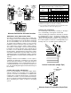
*If the appliance room is located against an outside wall and the air openings communicate
directly with the outdoors, each opening shall have a free area of not less than one square inch
per 4,000 BTU per hour of the total input rating of all appliances in the enclosure.
Equipment Located in Confined Spaces; All
Air from Outdoors. See 5.3.3-b.
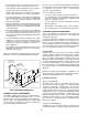
4. When ducts are used, they shall be of the same cross-
sectional area as the free area of the openings to which they
connect. The minimum dimension of rectangular air ducts
shall not be less than 3 inches.
5.3.4 Specially Engineered Installations:
The requirements of 5.3.3 shall not necessarily govern when special
engineering, approved by the authority having jurisdiction, pro-
vides an adequate supply of air for combustion, ventilation, and
dilution of flue gases.
5.3.5 Louvers and Grilles:
In calculating free area in 5.3.3, consideration shall be given to the
blocking effect of louvers, grilles or screens protecting openings.
Screens used shall not be smaller than 1/4 inch mesh. If the area
through a design of louver or grille is known, it should be used in
calculating the size of opening required to provide the free area
specified. If the design and free area is not known, it may be
assumed that wood louvers will have 20-25 percent free area and
metal louvers and grilles will have 60-75 percent free area. Louvers
and grilles shall be fixed in the open position or interlocked with the
equipment so that they are opened automatically during equipment
operation.
5.3.6 Special Conditions Created by Mechanical Exhausting or
Fireplaces:
Operation of exhaust fans, ventilation systems, clothes dryers, or
fireplaces may create conditions requiring special attention to avoid
unsatisfactory operation of installed gas utilization equipment. Air
from Inside Building. See 5.3.3-a.
VI. Installation Positions
This furnace may be installed in an upright position or
horizontal on either the left or right side panel. Do not
install this furnace on its back. For
upright upflow
furnaces,
return air ductwork may be attached to the side panel(s)
and/or basepan. For
horizontal upflow
furnaces, return air
ductwork must be attached to the basepan. For both
upright or horizontal counterflow
furnaces, return ductwork
must be attached to the basepan (top/end of the blower
compartment). Ductwork must never be attached to the
back of the furnace. Refer to the product Specifications
Sheet for proper airflow requirements and number of
required ductwork connections. Refer to “Recommended
Installation Positions” figure for appropriate installation
positions, ductwork connections, and resulting airflow ar-
rangements.
VII. Horizontal Applications and
Considerations
GENERAL
Horizontal applications, in particular, may dictate many of
the installation’s specifics such as airflow direction, duct-
work connections, flue and combustion air pipe connec-
tions, etc. The basic application of this furnace as a
horizontal furnace differs only slightly from an upright
installation. When installing a furnace horizontally, addi-
tional consideration must be given to the following:
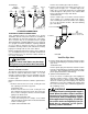
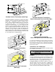
ALTERNATE VENT/FLUE
AND COMBUSTION AIR
INTAKE LOCATIONS
FURNACE MUST BE LEVEL
FROM END TO END
FURNACE MUST BE LEVEL
OR SLIGHTLY TILTED FORWARD
WITH THE DOORS 0" - 3/4"
BELOW THE BACK PANEL
DRAIN LINE WITH 1/4" PER FOOT
DOWNWARD SLOPE
36" MINIMUM SERVICE
CLEARANCE REQUIRED
FURNACE MUST BE SUPPORTED
AT BOTH ENDS AND MIDDLE
DRAIN PAN
GAS LINE WITH
DRIP LEG (3" MINIMUM)
4 3/4" MINIMUM
DRAIN TRAP
CLEARANCE
Horizontal Furnace
DRAIN TRAP AND LINES
In horizontal applications the condensate drain trap is
secured to the furnace side panel, suspending it below the
furnace. A minimum clearance of 4 3/4 inches below the
furnace must be provided for the drain trap. Additionally,
the appropriate downward piping slope must be main-
tained from the drain trap to the drain location. Refer to
Section X, Condensate Drain Trap and Lines
for further
details. If the drain trap and drain line will be exposed to
temperatures near or below freezing, adequate measures
must be taken to prevent condensate from freezing.
LEVELING
Leveling ensures proper condensate drainage from the
heat exchanger and induced draft blower. For proper flue
pipe drainage, the furnace must be level lengthwise from
end to end. The furnace should also be level from back to
front or have a slight tilt with the access doors downhill
(approximately 3/4 inches) from the back panel. The slight
tilt allows the heat exchanger condensate, generated in
the recuperator coil, to flow forward to the recuperator coil
front cover.