
Instruction manual


24
WARNING
To avoid the risk of electrical shock, injury,
or death, the furnace must be electrically
grounded in accordance with local codes
or, in their absence, with the latest edition
of The National Electric Code.
To ensure proper unit grounding, the ground wire should
run from the furnace ground screw located inside the
furnace junction box all the way back to the electrical panel.
NOTE: Do not use gas piping as an electrical ground. To
confirm proper unit grounding, turn off the electrical power
and perform the following check.
1. Measure resistance between the neutral (white) con-
nection and one of the burners.
2. Resistance should measure 10 ohms or less.
This furnace is equipped with a blower door interlock
switch which interrupts unit voltage when the blower door
is opened for servicing. Do not defeat this switch.
24 VOLT THERMOSTAT WIRING
NOTE: Wire routing must not interfere with circulator blower
operation, filter removal, or routine maintenance.
Low voltage connections can be made through either the
right or left side panel. Thermostat wiring entrance holes
are located adjacent to the junction box locations in the
blower compartment. Wire routing must not to interfere
with circulator blower operation, filter removal, or routine
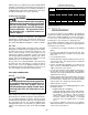
maintenance. Refer to the following figure for thermostat
connections to the integrated control module terminal
strip.
W
W
W
Y
Y
Y
C
C
R
R
R
G
G
W
Y
C
R
G
HEATING
ROOM
THERMOSTAT
HEATING AND
COOLING ROOM
THERMOSTAT
FURNACE
FURNACE
REMOTE
CONDENSING
UNIT
Thermostat Diagram
This furnace is equipped with a 40 VA transformer to
facilitate use with most cooling equipment. Consult the
wiring diagram, located on the blower compartment door,
for further details of 115 Volt and 24 Volt wiring.
WARNING
In upright upflow installations, the drain
trap must be mounted on the opposite side
of the unit from the junction box. This will
reduce the risk of water reaching the
junction box in the event of a blocked drain
condition.
Connect hot, neutral, and ground wires as shown in the
wiring diagram located on the unit’s blower door. Line
polarity must be observed when making field connections.
Line voltage connections can be made through either the
right or left side panel. The furnace is shipped configured
for a left side (right side for counterflows) electrical connec-
tion with the junction box located inside the blower com-
partment. To make electrical connections through the
opposite side of the furnace, the junction box must be
relocated to the other side of the blower compartment prior
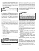
to making electrical connections. To relocate the junction
box, follow the steps shown below.
NOTE: Wire routing must not to interfere with circulator
blower operation, filter removal, or routine maintenance.
CAUTION
Edges of sheet metal holes may be sharp.
Use gloves as a precaution when removing
hole plugs.
1. Remove the blower compartment door.
2. Remove and save the two screws securing the junc-
tion box to the side panel.
3. Relocate junction box and associated plugs and grom-
mets to opposite side panel. Secure with screws
removed in step 2.
4. Verify that wires will not interfere with circulator blower
operation, filter removal, or routine maintenance.
STANDARD
JUNCTION BOX
LOCATION
ALTERNATE
JUNCTION BOX
LOCATION
Junction Box Relocation