
Instruction manual

38
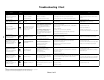
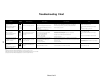
Troubleshooting Chart
Sheet 1 of 2
Notes:
1) Integrated control module will automatically attempt to reset from lock out after one hour.
2) LED flash code will cease if power to the control module is interrupted through the disconnect or door switch.
3) Integrated control module will automatically attempt to reset from lock out after 20 minutes.
Symptoms of Abnormal
Operation
Associated
LED Code
(See Note 2)
Fault Description(s) Possible Causes
- Furnace fails to operate.
and
- Inte
g
rated control module dia
g
nostic
LED provides no si
g
nal.
None
- No 115 V power to furnace, or no 24 V
power to inte
g
rated control module.
- Blown fuse, or circuit breaker.
- No si
g
nal from thermostat.
- Manual disconnect switch OFF, door switch open,
or 24 V wires miswired, loose or misconnected wires.
- Blown fuse, or circuit breaker.
- Improper thermostat connection or settin
g
.
- Furnace fails to operate.
and
- Inte
g
rated control module dia
g
nostic
LED is lit continuously.
Continuous
On
- Inte
g
rated control module has an
internal fault.
- Inte
g
rated control module has an
internal fault.
- Furnace is not operatin
g
- Furnace lockout due to an excessive
- Failure to establish flame. Cause may be no
g
as
to burners, front cover pressure switch stuck open,
bad i
g
niter or i
g
niter ali
g
nment, improper
orifices, or coated/oxidized or misconnected
and
- Inte
g
rated control module dia
g
nostic
LED is flashin
g
one flash. 1 Flash
number of i
g
nition "retries" (3 total
attempts), or "recycles" (5 total
recycles). See note 1.
flame sensor.
- Loss of flame after establishment. Cause
may be interrupted
g
as supply, lazy burner flames
(
improper
g
as pressure or restriction in flue
and/or combustion air pipin
g
), front cover pressure
switch openin
g
, or improper induced draft blower
performance.
- Furnace fails to operate.
and
- Inte
g
rated control module dia
g
nostic
LED is flashin
g
two flashes.
2 Flashes
- Pressure switch circuit is closed
even thou
g
h induced draft blower
is not operatin
g
.
- Induced draft blower pressure switch contacts stickin
g
.
- Shorts in pressure switch circuit.
- Induced draft blower runs continuously
with no further furnace operation.
and
- Inte
g
rated control module dia
g
nostic
LED is flashin
g
three flashes.
3 Flashes
- Pressure switch circuit does not
close in response to induced draft
blower operation.
- Pressure switch hose blocked, pinched, or
misconnected.
- Blocked flue and/or inlet air pipe, blocked drain
system, or weak induced draft blower.
- Incorrect pressure switch set point or
malfunctionin
g
switch contacts.
- Loose or misconnected wirin
g
.
- Circulator blower runs continuously
with no further furnace operation.
and
- Inte
g
rated control module dia
g
nostic
LED is flashin
g
four flashes.
4 Flashes
- Primary limit circuit is open.
(Primary or auxiliary limit).
- Insufficient conditioned air over the heat exchan
g
er.
Cause may be blocked filters, restrictive
ductwork, improper circulator blower speed, or
failed circulator blower.
- Loose or misconnected wirin
g
.
- Circulator blower runs continuously
with no further furnace operation.
and
- Inte
g
rated control module dia
g
nostic
LED is flashin
g
five flashes.
5 Flashes
- Rollout limit circuit is open.
- Rollout limit(s) is(are) open due to flame rollout.
Cause may be misali
g
ned burners, blocked flue
and/or air inlet pipe, or failed induced draft blower.
- Loose or misconnected wirin
g
.
- Furnace fails to operate.
and
- Inte
g
rated control module dia
g
nostic
LED is flashin
g
six flashes.
6 Flashes
- Polarity of 115 V or 24 VAC power
is reversed.
- Polarity of 115 VAC power to furnace or
inte
g
rated control module is reversed.
- Oran
g
e and
g
ray wires to transformer are reversed.
- Poor unit
g
round.
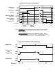
1
1
3
4
5
6
ON
2
Corrective Action
Cautions and
Notes
- Assure 115 V and 24 V power to furnace and inte
g
rated
control module.
- Check inte
g
rated control module fuse (3 A). Replace if necessary.
- Check for possible shorts in 115 V and 24 V circuits. Repair as necessary.
- Turn power OFF prior to repair.
- Replace inte
g
rated control module fuse with 3 A automotive
style fuse.
- Replace bad inte
g
rated control module with known
g
ood control module.
- Turn power OFF prior to repair.
- Read precautions in "Electrostatic Dischar
g
e"
section of manual.
- Locate and correct
g
as interruption.
- Check front cover pressure switch operation (hose, wirin
g
, contact operation).
Correct if necessary.
- Turn power OFF prior to repair.
- Replace or reali
g
n i
g
niter.
- Check flame sense si
g
nal. Sand sensor if coated/oxidized.
- I
g
nitor is fra
g
ile, handle with care.
- Sand flame sensor with emery cloth
- See "Flue and Combustion Air Pipe" section for pipin
g
details.
- Check flue pipin
g
for blocka
g
e, proper len
g
th, elbows, and termination.
- Verify proper induced draft blower performance.
- Replace induced draft blower pressure switch if bad.
- Check for and correct shorted wirin
g
.
- Turn power OFF prior to repair.
- Replace pressure switch with proper replacement part.
- Check and correct pressure switch hose.
- Check flue and/or inlet air pipin
g
for blocka
g
e, proper len
g
th, elbows
and termination. Check drain system.
- Verify proper pressure switch set point and contact motion.
- Check and correct wirin
g
.
- Turn power OFF prior to repair.
- See "Flue and Combustion Air Pipe" section for pipin
g
details.
- Replace pressure switch with proper replacement part.
- Check filters and ductwork for blocka
g
e. Clean filters or remove obstruction.
- Check for proper circulator blower speed and performance. Correct speed or
replace blower if necessary.
- Check and correct wirin
g
.
- Turn power OFF prior to repair.
- See Specification Sheet for allowable rise ran
g
e and proper
circulator blower speed.
- Check burners for proper ali
g
nment.
- Check flue and/or air inlet pipin
g
for blocka
g
e, proper len
g
th, elbows, and termination.
- Check induced draft blower for proper performance. Replace if necessary.
- Check and correct wirin
g
.
- Turn power OFF prior to repair.
- See "Flue and Combustion Air Pipe" section for pipin
g
details.
- Replace induced draft blower with proper replacement part.
- Review wirin
g
dia
g
ram.
- Verify proper
g
roundin
g
.
- Check and correct wirin
g
.
- Turn power OFF prior to repair.