
Instruction manual

39
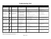
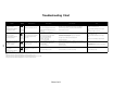
Troubleshooting Chart
Sheet 2 of 2
Notes:
1) Integrated control module will automatically attempt to reset from lock out after one hour.
2) LED flash code will cease if power to the control module is interrupted through the disconnect or door switch.
3) Integrated control module will automatically attempt to reset from lock out after 20 minutes.
Symptoms of Abnormal
Operation
Associated
LED Code
(See Note 2)
Fault Description(s) Possible Causes
- Induced draft and circulator blower run
continuously with no further
furnace operation.
and
- Inte
g
rated control module dia
g
nostic
LED is flashin
g
continuously.
Continuous
Flashin
g
- Flame has been sensed with no call
for heat.
- Short to
g
round in flame sense circuit.
- Limit circuit (primary or auxiliary) has
opened five times durin
g
a sin
g
le call
for heat. See note 1.
- Insufficient conditioned air over the heat exchan
g
er.
Cause may be blocked filters, restrictive
ductwork, improper circulator blower speed, or
failed circulator blower.
- Loose or misconnected wirin
g
.
- Pressure switch circuit has opened five
times durin
g
a sin
g
le call for heat.
See note 3.
- Pressure switch hose blocked, pinched, or
misconnected.
- Blocked flue and/or inlet air pipe, blocked drain
system, or weak induced draft blower.
- Incorrect pressure switch set point or
malfunctionin
g
switch contacts.
- Loose or misconnected wirin
g
.
- Circulator blower runnin
g
continuously
with no further furnace operation
and
- Inte
g
rated control module dia
g
nostic
LED is flashin
g
nine flashes.
9 Flashes
- Furnace is not operatin
g
and
- Inte
g
rated control module dia
g
nostic
LED is flashin
g
ei
g
ht flashes.
8 Flashes
7 Flashes
- Normal furnace operation.
but
- Inte
g
rated control module dia
g
nostic
LED is flashin
g
seven flashes.
- Flame sense micro-amp si
g
nal is low.
- Flame sensor is coated/oxidized.
- Flame sensor incorrectly positioned in burner flame.
- Lazy burner flame due to improper
g
as pressure, or
combustion air.
C
White-Rodgers
Control Only
7
Heatcraft
Control Only
8
9
Heatcraft
Control Only
Corrective Action
Cautions and
Notes
- Correct short at flame sensor or in flame sensor wirin
g
. - Turn power OFF prior to repair.
- Check filters and ductwork. For blocka
g
e . Clean filters or remove obstruction.
- Check for proper circulation blower speed and performance. Correct speed or replace
blower if necessary.
- Check and correct wirin
g
.
- Turn power OFF prior to repair.
- See Specification Sheet for allowable rise ran
g
e and proper
circulator blower speed.
- Check and correct pressure switch hose.
- Check flue and/or inlet air pipin
g
for blocka
g
e, proper len
g
th, elbows
and termination. Check drain system.
- Verify proper pressure switch set point and contact motion.
- Check and correct wirin
g
.
- Sand flame sensor if coated/oxidized. Inspect for proper sensor ali
g
nment.
- Check inlet air pipin
g
for blocka
g
e, proper len
g
th, elbows, and termination.
- Check for proper
g
as pressures.
- Turn power OFF prior to repair.
- Sand flame sensor with emery cloth.
- See "Flue and Combustion Air Pipe" section for pipin
g
details.
- See ratin
g
plate for proper
g
as pressures.
- Turn power OFF prior to repair.
- See "Flue and Combustion Air Pipe" section for pipin
g
details.
- Replace pressure switch with proper replacement part.