Technical Information Model and Manufacturing numbers listed on page 3. 40" 80% Gas Furnaces GUIS, GCIS • Refer to Service Manual RS6600001 Rev. 1 for installation, operation, and troubleshooting information. • All safety information must be followed as provided in the Service Manual. • Refer to the appropriate Parts Catalog for part number information. D E SI G N This manual replaces RT6621005 Rev. 0 April 2000. REV. 1 - Corrections made to manual, no new models added.
PRODUCT IDENTIFICATION The model and manufacturing number are used for positive identification of component parts used in manufacturing. When engineering and manufacturing changes take place where interchangeability of components are affected, the manufacturing number will change. It is very important to use the model and manufacturing numbers at all times when requesting service or parts information. G U I S 045 C A 50 Product Type Airflow Capability 30: 3.0 Tons G: Gas Furnace 35: 3.5 Tons 50: 5.
PRODUCT IDENTIFICATION The model and manufacturing number are used for positive identification of component parts used in manufacturing. When engineering and manufacturing changes take place where interchangeability of components are affected, the manufacturing number will change. It is very important to use the model and manufacturing numbers at all times when requesting service or parts information.
PRODUCT DESIGN General Operation This GUIS/GCIS furnace is equipped with an electronic ignition device to light the burners and an induced draft blower to exhaust combustion products. Location Considerations • The furnace should be as centralized as is practical with respect to the air distribution system. An interlock switch prevents furnace operation if the blower door is not in place. Keep the blower access doors in place except for inspection and maintenance.
PRODUCT DESIGN High Altitude Derate When this furnace is installed at high altitude, the appropriate High Altitude orifice kit must be installed. This is required due to the natural reduction in the density of both the gas fuel and combustion air as altitude increases. The kit will provide the proper design certified input rate within the specified altitude range. PROPANE AND HIGH ALTITUDE KITS MODEL NUMBER 0 to 7000 ft. 3001 to 7000 ft. 7001 to 8500 ft. 7001 to 8500 ft.
PRODUCT DIMENSIONS GUIS 80% Upflow/Horizontal UPFLOW LEFT SIDE VIEW 28 3/4 A KNOCK-OUT FOR HORIZONTAL VENTING 28 3/4 UPFLOW RIGHT SIDE VIEW UPFLOW FRONT VIEW 20 1/8 B 3/4 4 3/4 3/4 C 4 5/8 1 3/4 ELECTRICAL HOLE "HIGH VOLTAGE" SUPPLY ELECTRICAL HOLE "LOW VOLTAGE" SUPPLY GAS SUPPLY HOLE A Raytheon Company 40 4 5/8 31 37 3/8 23 34 5/8 31 5/8 28 1/4 14 SIDE KNOCK-OUT SIDE KNOCK-OUT 1 5/8 1 5/8 23 BOTTOM KNOCK-OUT D BOTTOM KNOCK-OUT GUIS DIMENSIONS B C D E Minimum Vent Diameter
PRODUCT DIMENSIONS GCIS 80% Counterflow/Horizontal COUNTERFLOW FRONT VIEW A 3/4 COUNTERFLOW RIGHT SIDE VIEW COUNTERFLOW LEFT SIDE VIEW 28 3/4 B 3/4 28 20 1/8 3/4 3" 4 3/4 22 28 1/4 4 5/8 31 5/8 34 5/8 KNOCK-OUT FOR HORIZONTAL VENTING 40 31 GAS SUPPLY HOLE A Raytheo nC ompan y SUPPLY ELECTRICAL HOLE "LOW VOLTAGE" 18 5/8 UNFOLDED FLANGES 20 1/8 FOLDED FLANGES D UNFOLDED FLANGES E FOLDED FLANGES SUPPLY ELECTRICAL HOLE "HIGH VOLTAGE" 1 3/4 2 1/2 Units are shipped with unfolded bottom fla
PRODUCT DESIGN PRESSURE SWITCH TRIP POINTS AND USAGE CHART NEGATIVE PRESSURE ID BLOWER WITH FLUE NOT FIRING TYPICAL SEA LEVEL DATA LOW HIGH FIRE FIRE NEGATIVE PRESSURE ID BLOWER WITH FLUE FIRING TYPICAL SEA LEVEL DATA LOW HIGH FIRE FIRE GUIS070**35 -0.50 -0.90 -0.52 -0.85 GUIS090**30/50 -0.42 -0.9 -0.44 -0.79 GUIS115**50 -0.42 -0.85 -0.42 -0.71 GUIS140**50 -0.37 -0.85 -0.39 -0.71 GCIS070**35 -0.32 -0.80 -0.37 -0.60 GCIS090**50 -0.32 -0.80 -0.37 -0.
PRODUCT DESIGN T.O.D.
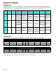
PRODUCT DESIGN Coil Matches: A large array of Amana coils are available for use with the GUIS and GCIS furnaces, in either upflow, counterflow, or horizontal applications. These coils are available in both cased and uncased models, with or without a TXV expansion device. These 80% furnaces match up with the existing Amana coils as shown in the chart below.
FURNACE SPECIFICATIONS MODEL Btuh Input (US) High Fire GUIS070CA35 GUIS070CX35 GUIS070DA35 GUIS090CA30 GUIS090CX30 GUIS090CA50 GUIS090CX50 GUIS115CA50 GUIS140CA50 69,000 92,000 92,000 115,000 138,000 Output (US) High Fire 55,200 73,600 73,600 92,000 110,400 Btuh Input (US) Low Fire 48,000 64,000 64,000 80,000 96,000 Output (US) Low Fire 38,400 51,200 51,200 64,000 76,800 80% 80% 80% 80% 80% Rated External Static (" w.c.) .10 - .50 .10 - .50 .10 - .50 .10 - .50 .10 - .
FURNACE SPECIFICATIONS MODEL GCIS070CX35 GCIS090CX50 Btuh Input (US) High Fire 69,000 92,000 Output (US) High Fire 55,200 73,600 Btuh Input (US) Low Fire 48,000 64,000 Output (US) Low Fire 38,400 51,200 80% 80% Rated External Static (" w.c.) A.F.U.E. .10 - .50 .10 - .50 Temperature Rise (°F) 35 - 65 45 - 75 -0.55 -0.55 High Stage Pressure Switch Trip Point (" w.c.) Low Stage Pressure Switch Trip Point (" w.c.) -0.27 -0.
BLOWER PERFORMANCE SPECIFICATIONS (CFM & Temperature Rise vs.
BLOWER PERFORMANCE SPECIFICATIONS 14 Rev. 1 BTU OUTPUT vs TEMPERATURE RISE CHART 100 600 CFM 90 700 80 800 TEMPERATURE RISE 900 1000 70 1100 1200 60 1400 1600 50 1800 2000 2200 2400 CFM 40 30 FORMULAS BTU OUTPUT = CFM x 1.08 x RISE BTU OUTPUT RISE = ÷ CFM 1.
Y 7 (PS1) PRESSURE SWITCH (LOW) (PS2) PRESSURE SWITCH (HIGH) BR BR CONTROL R TERMINAL ORDER REARRANGED FOR CLARITY COM 5 6 ** * X X MF F M RR M V C HNH NH HN P H H MC MP O OEO E OOE T T S L L V OV S O T UT UT T U RH1 I OL MH2 L * P A R K ** H E A T L O H I E I N A G D G i T I N HG- F N H I NN P D I C I R N E U COOL 5 HI 3 OR-20 C 2 BR-21 PM 1 GY-47 GAS VALVE (GV) GY-47 YL-11 BU-12 HEAT-HI BK-6 BK-1 LINE XMFR EAC HUM GN IGN IND-HI HUM MVH EAC PS2 CIR GND XFMR WH-33 F
W2 Y (PS1) PRESSURE SWITCH (LOW) 7 (PS2) PRESSURE SWITCH (HIGH) BR BR CONTROL R TERMINAL ORDER REARRANGED FOR CLARITY COM 5 B 6 *** XX MF F M RR M V HNH NHHN P H H MC MP OE O E OOE T T S L L V OV S T UT UT T U R H1 I OL MH2 ** * C O O L P A R K H E A T L O H I E I N A G D T I N Gi HG- F NH I NNP DI C I R N E U 2 BR-21 PM 1 GY-47 C GAS VALVE (GV) HEAT-HI LINE XMFR EAC HUM GN IGN IND-HI CIR WH-33 EAC HUM NC BK-6 BU-36 8 WH-23 ON WH-23 G A PM 1 S PRIMARY RL F L A M E V
GUIS and GCIS WR50A51-215 INTEGRATED IGNITION CONTROL This schematic is for reference only. Not all wiring is as shown above, refer ! WARNING IGNN 1M 1M .