
Operating instructions


SERVICING
107
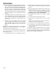
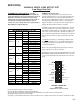
THERMOSTAT HEAT INPUT(S): R, W1
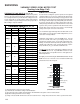
First, low voltage readings are measured with the
16-pin wire harness disconnected from the motor. A
diagram of the harness and pin locations is pro-
vided below. Voltage measurement is AC or DC as
specified in the chart below under the (Volts)
column. Set your voltage meter to the proper AC or
DC reading as requested below.
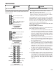
VARIABLE SPEED (ECM) MOTOR TEST
(Low Stage Heat Call)
CONTROL CONNECTOR
"Motor Half“
(Viewed from connector end)
(1) This input must be active for motor to operate.
(2) 0 VAC indicates humidistat is calling for dehumidification.
(3) These two pins form an output circuit that powers the CFM LED on the ignition control or interface board.
(4) Dipswitch settings determine measure voltage.
(5) Voltage is measured with 16-wire harness disconnected from motor. Voltage measurement is AC or DC as specified in the chart.
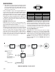
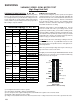
ECM Motor Not Coming On
In order for the heating fan speed to operate, the inte-
grated control board has to receive a low-stage (W1) call
from the thermostat. The control board now starts the
heat sequence, bringing on the burners. After the control
board goes through its timing sequence, the following
signals should be seen at the end of the 16 pin harness
going to the motor while the burners are firing.
Unplug the 16-pin harness from the ECM motor. Set volt
meter to read AC volts. Place your voltage meter on Pin
1(Common) and Pin 2 (W1), you should be reading 13 AC
volts. Next, check between Pin 1 (Common) and Pin 12
(R), you should read 24 AC volts. Finally, check between
Pin 1(Common) and Pin 15 (G), you should read 13 AC
Volts.
You MUST have all of these low voltage readings before
the ECM motor will come on. If you DO NOT have these
readings you may have a 16-pin harness or integrated
control board problem.
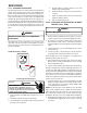
Make sure you have high voltage at the 5-pin connector
going to the motor as discussed earlier.
We highly recommend using the GE TECMate XL™ or the
GE TECMate PRO™ model ECM motor tester. This low
cost test instrument will verify whether the motor itself is
good.
ADJUST +/-
Y 1
COOL
COMMON 2
COMMON 1
OUT +
EM HT/W2
24VAC (R)
BK/Pwm (Speed)
O (Rev Valve)
8
16
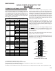
Description Pin
Volts
(5)
Signal Indicates
Com, C1 1 0 VAC Common
W/W1 2
≥
13 VAC W1 = ON
Com, C2 3 0 VAC Common
0 VAC Delay Tap = A
≥
10 VDC Delay Tap = B
≤
-10 VDC Delay Tap = C
24 VAC Delay Tap = D
0 VAC Cool Tap = A
≥
10 VDC Cool Tap = B
≤
-10 VDC Cool Tap = C
24 VAC Cool Tap = D
Y1 6 0 VAC Y1 = OFF
0 VAC Adjust Tap = A
≥
10 VDC Adjust Tap = B
≤
-10 VDC Adjust Tap = C
24 VAC Adjust Tap = D
Out -
(3)
8 0 VDC Common
O90 VACO = OFF
Bk/PWM
(2)
10 24 VAC No Dehumidification
0 VAC Heat Tap = A
≥
10 VDC Heat Tap = B
≤
-10 VDC Heat Tap = C
24 VAC Heat Tap = D
R1224 VACR = ON
EM/W2 13 0 VAC EM/W2 = OFF
Y/Y2 14 0 VAC Y/Y2 = OFF
G
(1)
15
≥
13 VAC G = ON
Out +
(3)
16 0-3.5 VDC CFM LED
Thermostat Input(s): R, W1
Delay
(4)
4
Cool
(4)
5
Adjust
(4)
7
Heat
(4)
11