
Operating instructions


SERVICING
125
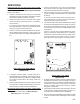
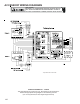
Amana® brand 80% and 90% Single-Stage (ADS8,
AMS8, ACS9, AMS9, AMS95)
NOTE: The models above use White-Rodgers 50A65-289
ignition control board.
1. Check for 120 volts from Line 1 (Hot) to Line 2 (Neutral)
at the ignition control. No voltage, check the door switch
connections and wire harness for continuity.
2. Check for 24 volts from W to C terminal on the ignition
control. No voltage. Check transformer, room thermo-
stat, and wiring.
If you have 24 volts coming off the transformer but re-
ceive approximately 13 volts on the terminal board be-
tween (C) and (R), check for blown fuse.
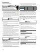
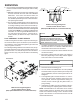
3. Check for 120 volts to the induced draft blower by mea-
suring voltage between terminals 1 and 4 (on the 4-pin
connector) shown below. No voltage, replace ignition con-
trol.
FUSE
OF F
ON
2
1
E1
CGRWY
E1 8
E1 6
E1 7 E2 8 E2 7 E1 3
E14
E2 0
CIR-N
XFMR -N
EAC-N
HUM-N
E11
E10
E9
E8
E7
LINE-N
HUM-HXFM R-HE AC- HHEAT-H
LINE-H
PARK
PA R K
COOL-H
102077 20
1
2
3
4
(ADS8, AMS8, ACS9, AMS9, AMS95)
(WR50A65-289)
4. If voltage is present in Steps 1 through 3 and the in-
duced draft blower is operating, check voltage to the ig-
nitor during the preheat cycle. Measure voltage between
Pin 2 and Pin 3 shown above. No voltage, check pres-
sure switch.
5. After the ignitor warmup time, begin checking for 24 volts
to the gas valve. Voltage will be present for seven sec-
onds only if proof of flame has been established.
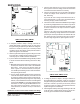
Amana® brand 80% and 90% Two-Stage (ADV8, AMV8,
ACV9, AMV9)
NOTE: The models above use White-Rodgers
50V61-289 ignition control board.
1. Check for 120 volts from Line 1 (Hot) to Line 2 (Neutral)
at the ignition control. No voltage, check the door switch
connections and wire harness for continuity.
2. Check for 24 volts from W1 to C terminal on the ignition
control. No voltage. Check transformer, room thermostat,
and wiring.
If you have 24 volts coming off the transformer but re-
ceive approximately 13 volts on the terminal board be-
tween (C) and (R), check for blown fuse.
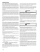
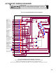
3. Check for 120 volts to the induced draft blower (low-stage)
by measuring voltage between Pin 3 and Pin 4 (on the 5-
pin connector) shown below. No voltage, check for loose
connection in the 5-pin connector or replace ignition control
shown below.
Check for 120 volts to the induced draft blower (high-
stage) by measuring voltage between Pin 2 and Pin 4
(on the 5-pin connector) shown below. No voltage, check
for loose connection in the 5-pin connector, no call for
high stage heat or replace ignition control show below.
USC
1
2
3
4
5
LO HEAT HI HEAT E AC CO OL PA RK LIN E XFMR HUM
HOT NEUTRAL
LO HEAT HI HEAT E AC CO OL PA RK LIN E X FMR H UM
SWITCH
WHITE RODGERS
CFM
DEHUM
CUT FOR
1
2
3
TSTAT
S4
S3
OFF
ON
S1
S
I
N
G
L
E
T
W
O
ON
OFF
87654321
87654321
20300
0-
0
6
(ADV8, AMV8, ACV9, AMV9)
(WR50V61-289)
4. If voltage is present in Steps 1 through 3 and the induced
draft blower is operating, check for voltage to the ignitor
during the preheat cycle. Measure voltage between Pin
1 and Pin 5 (on the 5-pin connector) shown on previous
picture. No voltage, check pressure switch or replace
the ignition control board.
5. After the ignitor warmup time, begin checking for 24 volts
to the gas valve. Voltage will be present for seven sec-
onds only if proof of flame has been established.
6. If proof of flame was established voltage will be provided
to the air circulation blower following the heat on delay
period.