
Operating instructions
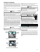

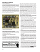


PRODUCT DESIGN
64
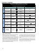
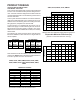
24 VOLT T HERMOSTAT WIRING
NOTE: Wire routing must not interfere with circulator blower
operation, filter removal, or routine maintenance.
As a two-stage furnace, the furnace integrated control
module provides terminals for both “W1” and “W2”, and
“YLO” and “Y” thermostat connections. This allows the
furnace to support the following system applications: ‘Two-
Stage Heating Only’, ‘Two-Stage Heating with Single-Stage
Cooling’, and ‘Two-Stage Heating with Two-Stage Cooling’.
Refer to the following figures and table for proper connec-
tions to the integrated control module.
Mode
Furnace Circulator Blower Operation
During Call From Thermostat
24 Volts HOT R
From Room
Thermostat
R
On Two-Stage
Integrated
Control Module
N/A
24 Volts COMMON C
From Room
Thermostat
C
On Two-Stage
Integrated
Control Module
N/A
Low Stage Connection
For
"Two-Stage" Heating
W1
From Room
Thermostat
W1
On Two-Stage
Integrated
Control Module
Circulator blower will operate on selected
Low Stage Heating
speed tap
High Stage Connection
For
"Two-Stage" Heating
W2
From Room
Thermostat
W2
On Two-Stage
Integrated
Control Module
Circulator blower will operate on selected
High Stage Heating
speed tap
Connection For
"Single-Stage" Cooling
Y
From Room
Thermostat
Y
On Two-Stage
Integrated
Control Module
Circulator blower will operate on selected
High Stage Cooling
speed tap (5 second "ON"
delay and 45 second "OFF" delay)
Low Stage Connection
For
"Two-Stage" Cooling
Y1
From Room
Thermostat
Y-LO
On Two Stage
Integrated Control
Module
Circulator blower will operate at 65% of
selected High Stage Cooling
speed tap
High Stage Connection
For
"Two-Stage" Cooling
Y2
From Room
Thermostat
Y
On Two-Stage
Integrated
Control Module
Circulator blower will operate on selected
High Stage Cooling
speed tap (5 second "ON"
delay and 45 second "OFF" delay)
CONTINUOUS
FAN
Continuous Fan
Connection
[Any Application]
G
From Room
Thermostat
G
On Two-Stage
Integrated
Control Module
Circulator blower will operate at
56% of selected
High Stage Cooling Speed Tap
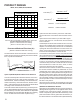
GENERALHEATINGCOOLING
Thermostat Wiring Reference Chart
Two-Stage Variable Speed Furnace
Thermostat Connection Connection Options
( ADV8, AMV8, ACV9, AMV9, GMV8, GCV9, GMV9, GMV95 )
To
To
To
To
To
To
To
To
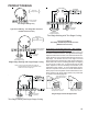
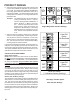
Low voltage connections can be made through either the
right or left side panel. Thermostat wiring entrance holes
are located in the blower compartment. The following figure
shows connections for a “heat only” system and “heat/cool
system”.
This furnace is equipped with a 40 VA transformer to facili-
tate use with most cooling equipment. Consult the wiring
diagram, located on the blower compartment door, for fur-
ther details of 115 Volt and 24 Volt wiring.