
Operating instructions

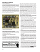


PRODUCT DESIGN
70
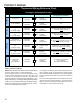
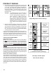
AMV9, ACV9, GMV9, GCV9, GMV95
600 800 1000 1200 1400 1600 2000
0453__XA 376* 384 480 576 --- --- ---
0704__XA --- --- 627* 627* 672 768 ---
0905__XA --- --- --- 836* 836* 836* 960
1155__XA --- --- --- 940* 940* 940* 960
600 800 1000 1200 1400 1600 2000
0704__XA --- --- 320* 320* 336 384 ---
0905__XA --- --- --- 427* 427* 427* 480
Input__Airflow
UPFLOW
COOLING AIRFLOW REQUIREMENT (CFM)
COUNTERFLOW
COOLING AIRFLOW REQUIREMENT (CFM)
Input
Airflow
*Minimum filter area dictated by heating airflow requirement.
Permanent Minimum Filter Area (sq. in)
[Based on a 600 ft/min filter face velocity]
[Based on 300 ft/min filter face velocity]
Permanent Minimum Filter Area (in
2
)
[Based on 600 ft/min filter face velocity]
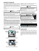
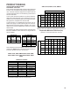
The sketch below shows how the filter is retained over the
bottom return air opening on (Upflow) 90% furnace installa-
tions only with kit # RF000180.
FILTER
FILTER
RETAINER
FURNACE FRONT
FURNACE BOTTOM
CAPTIVE LANCES
IN BACK PANEL
Optional (RF000180) Bottom Return Filter Retention
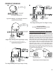
One inch throwaway filters should be sized for a face veloc-
ity of 300 feet per minute or less (14x25x1 throwaway = 730
CFM maximum, 16x25x1 throwaway = 830 CFM maximum,
18x25x1 throwaway = 940 CFM maximum, 20x25x1 throw-
away = 1040 CFM maximum) All other filters should be sized
according to their manufacturer's instructions.
To find the miminum filter requirement (in
2
) for either perma-
nent or disposable filters divide the required airflow (CFM) by
the rated velocity of the filter, either 300ft/min for disposable
filter or 600ft/min for permanent filter. Multiply the number by
144 in.
2
to obtain the minimum filter requirement (in
2
).
EXAMPLE:
Filter Size (in
2
) =
1400 CFM x 144 in
2
600 ft./min. (Permanent)
Filter Size (in
2
) =
1400 CFM x 144 in
2
300 (Disposable) ft./min.
Filter Size = 672in
2
Disposable
Filter Size = 336in
2
Permanent
Upflow furnaces with air delivery of less than 1800 CFM:
Use one side return or one bottom return ductwork connec-
tion.
Upflow furnaces with air delivery of 1800 CFM or higher:
Use two side returns or one side return and one bottom
return connection.
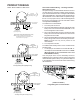
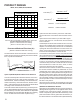
Guide dimples locate the side and bottom return cutout lo-
cations. Use a straight edge to scribe lines connecting the
dimples. Cut out the opening on these lines. An undersized
opening will cause reduced airflow. For bottom return con-
nection, remove the bottom of the cabinet before setting the
furnace on the raised platform or return air duct.
A closed return duct system must be used, with the return
duct connected to the furnace.
NOTE: Ductwork must never
be attached to the back of the furnace. Supply and return
connections to the furnace may be made with flexible joints
to reduce noise transmission, if desired. If a central return
is used, a connecting duct must be installed between the
unit and the utility room wall so the blower will not interfere
with combustion air or draft. The room, closet, or alcove
must not be used as a return air chamber.
When the furnace is used in connection with a cooling unit,
the furnace should be installed in parallel with or on the
upstream side of the cooling unit to avoid condensation in
the heating element. With a parallel flow arrangement, the
dampers or other means used to control the flow of air must
be adequate to prevent chilled air from entering the furnace
and, if manually operated, must be equipped with means to
prevent operation of either unit unless the damper is in the
full heat or cool position.
When the furnace is heating, the temperature of the return
air entering the furnace must be between 55°F and 100°F.
UPRIGHT FILTER INSTALLATIONS
Depending on the installation and/or customer preference,
differing filter arrangements can be applied. Filters can be
installed in the central return register, the bottom of the
blower compartment (upflow filter kit # RF000180), a side
panel external filter rack kit (upflow filter kit # EFR01), or
the ductwork above a counterflow furnace (kit # RF000181).