
Specifications

47 Rev. 3
COMBUSTION AND VENTILATION AIR
(GUD/GCD Direct Vent Models)
VENT PIPE INSTALLATION
1. Horizontal or Vertical
The size of the vent and air intake pipes is determined by
the heating capacity of the furnace and the length and num-
ber of elbows of the pipe runs. To properly size the pipes,
refer to the previous Section.
Use only the fittings, primer, and solvent cement which are
described on page 43 and 44. An air intake screen (as de-
scribed on page 45) must be installed. This screen is sup-
plied with the furnace. Do not place a screen in the exhaust
vent termination. It is not needed, and the furnace flue prod-
ucts could cause it to corrode.
WARNING
SOLVENT CEMENTS ARE COMBUSTIBLE LIQUIDS
AND SHOULD BE KEPT AWAY FROM ALL IGNITION
SOURCES. (IE: SPARKS, OPEN FLAMES, AND EXCES-
SIVE HEAT). AVOID BREATHING CEMENT VAPORS OR
CONTACT WITH SKIN AND EYES.
Under some conditions, insulation of some or all of the vent
pipe and/or combustion air pipe may be required. Do not
install insulation until after the flue system has been in-
spected for leaks as described below.
WARNING
UPON COMPLETION OF THE FURNACE INSTALLA-
TION, CAREFULLY INSPECT THE ENTIRE FLUE SYS-
TEM BOTH INSIDE AND OUTSIDE THE FURNACE TO
ASSURE IT IS PROPERLY SEALED. LEAKS IN THE
FLUE SYSTEM CAN RESULT IN SERIOUS PERSONAL
INJURY OR DEATH DUE TO EXPOSURE OF FLUE
PRODUCTS, INCLUDING CARBON MONOXIDE.
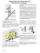
2. Horizontal Only
For each 2 inch pipe, drill a 2 3/8 inch diameter hole through
the wall at the proper location.
For each 3 inch pipe, drill a 3 1/2 inch diameter hole through
the wall at the proper location.
Cut a piece of PVC (ABS) pipe that is the thickness of the
wall plus the depth of the sockets of the fittings to be in-
stalled on the inside and outside of the walls.
To prevent the vent pipe from moving, and possibly dam-
aging the connections, locate the fittings on the inside wall
and the elbow on the outside as shown in the drawing of
the medium radius elbow dimensions on page 46 for the
air intake.
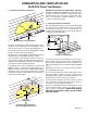
In a basement installation, the vent pipe may be run be-
tween the joist spaces. If the pipes must go below the joists,
then the pipes must run up into the last joist space to go
through the header. Two 45° elbows should be used rather
than 90's.
The horizontal run of exhaust pipe must not have any sag
that can hold condensate and should pitch up at least 1/4"
per foot so that condensate will run back to the unit to drain.
Support the horizontal run at least every three feet.
Allow for some expansion and contraction from tempera-
ture fluctuations. The normal direction changes usually ac-
count for this, but if you have a long run followed by a short
offset of less than 40 inches such as going up into the last
joist space, the pipes should be tightly clamped to prevent
flex loading on the fittings. Seal around the pipe on the out-
side wall with silicone caulking material.
ADDITIONAL CANADIAN VENTING REQUIREMENTS
In Canada venting shall conform to the requirements of the
current CANI-B149 Installation Codes.
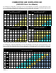
Use only C.S.A. listed 2" or 3" nominal diameter PVC or
ABS pipe and fittings throughout.
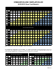
Refer to the following charts on pages 48 and 49 for the
correct inlet and exhaust pipe sizing.
A single wall vent shall not be run vertically through the
roof. Although, the vent may be run through an existing
unused
chimney as described in the previous venting sec-
tion provided the space between the vent pipe and the chim-
ney is insulated and closed with a weather tight, corrosion
resistant flashing.
Cut all vent pipe at right angles. Remove inside and out-
side burr at each cut. Use clean pipe and fitting socket.
Use CSA listed cement to fasten pipe and fittings. Follow
manufacturers cleaning and cementing instructions care-
fully to avoid leakage.
Note: ALL PIPING EXPOSED OUTDOORS OR IN UN-
HEATED AREAS MUST BE INSULATED WITH 1/2" THICK
CLOSED CELL FOAM INSULATION SUCH AS
"ARMAFLEX" OR "INSULTUBE".
The vent terminal shall NOT be located:
1. Less than 12" above the finished grade line.
2. Less than 36" from any building opening or any gas
service regulator (for gas service regulators in the Prov-
ince of Ontario, 72").
3. Less than 72" from the combustion air inlet of another
appliance.
4. Directly above a gas utility meter or service regulator.
5. Over a walkway unless 84" above grade.