
Service manual


Component Testing Procedures
!
WARNING
To avoid risk of electrical shock, personal injury, or death, disconnect power to oven and discharge capacitor
before servicing, unless testing requires it.
©2003 Maytag Appliances Company 16022150 Rev. 0 17
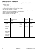
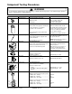
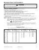
Illustration Component Test Results
Thermal cutout Disconnect all wires from TCO.
Measure resistance across terminals.
Magnetron TCO ..........................................
Cavity TCO.................................................
Open at (145°C) 293°F and
closed at (85°C) 185°F
Opens at (110°C) 230°F
Capacitor
Discharge Capacitors
Remove wires from capacitor terminals and
connect ohmmeter, set on highest
resistance scale to terminals.
Also check between each terminal and
capacitor case.
Between Terminals: Meter should
momentarily deflect towards zero then
return to over 5 MΩ.Ifnodeflection
occurs, or if continuous deflection
occurs, replace capacitor.
Terminal to Case: Infinite resistance
Diode assembly
Discharge Capacitors
Remove diode lead from capacitor and
connect ohmmeter.
Reverse leads for second test.
Infinite resistance should be measured
in one direction and 50KΩ or more in
the opposite direction.
NOTE: Analog meter must contain a
battery of 6 volts minimum.
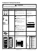
Magnetron
Discharge Capacitors
Remove wires from magnetron and connect
ohmmeter to terminals. Also check
between each terminal and ground.
Between Terminals: Less than 1 Ω
Each terminal to ground measures
infinite resistance.
Note: This test is not conclusive. If
oven does not heat and all other
components test good replace the
magnetron and re-test.
Turntable motor Remove all wires from terminals.
Measure resistance from:
Terminal to terminal
Approximately 12−14 KΩ
Fan motor Remove all wires from motor.
Measure resistance across coil.
Approximately 350−450 Ω
Secondary
Primary
Filament
Transformer
Discharge Capacitors
Remove all wires from terminals.
Measure resistance from:
Primary....................................................
Secondary to transformer base plate......
Filament ..................................................
Approximately 1.4 – 2.2 Ω
Approximately 90 - 110 Ω
<1 Ω
Secondary
switch
Monitor
switch
Primary
switch
COM
NO
NO
COM
COM
NC
Interlock switches Disconnect wires to switch
With door open measure resistance from:
COM to N.O.Primary.............................
COM to N.C.Monitor..............................
COM to N.O.Secondary ........................
With door closed measure resistance from:
COM to N.O.Primary.............................
COM to N.C.Monitor..............................
COM to N.O.Secondary ........................
Infinite Ω
0 Ω
Infinite Ω
0 Ω
Infinite Ω
0 Ω