This Base Manual covers International Commercial Microwave Ovens with 50 Hz. Refer to individual Technical Sheet for information on specific models. RC519M RC519M P1199603M P1199604M Service International Commercial Microwave Ovens Service Manual for Amana® This manual is to be used by qualified appliance technicians only. Amana does not assume any responsibility for property damage or personal injury for improper service procedures done by an unqualified person.
Important Information Pride and workmanship go into every product we produce to provide our customers with quality products. It is possible, however, that during its lifetime a product may require service. Products should be serviced only by a qualified service technician who is familiar with the safety procedures required in the repair and who is equipped with the proper tools, parts, testing instruments and the appropriate service manual.
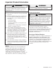
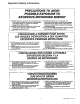
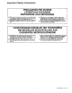
Important Product Information ! ! WARNING WARNING To avoid risk of electrical shock, injury, or death, make sure these earthing instructions are followed. Precautions to be observed before and during servicing to avoid possible exposure to excessive microwave energy, or electrical shock disconnect power to oven. Earthing Instructions (A) Do not operate or allow oven to be operated with door open.
Table of Contents Microwave Energy Leakage Testing Equipment ............................................................... 27 Procedure For Measuring Radiation Leakage ........ 27 Measurement With the Outer Panel Removed ....... 27 Measurement With a Fully Assembled Oven .......... 27 Record Keeping and Notification After Measurement .............................................. 27 Troubleshooting Initial Power Up ....................................................... 28 Stand By Condition .............
Important Safety Information 5 RS5320014 Rev.
Important Safety Information RS5320014 Rev.
Important Safety Information 7 RS5320014 Rev.
Important Safety Information ! 7. In the area of the transformer, capacitor, diode, and magnetron there is HIGH VOLTAGE. When the unit is operating, keep this area clean and free of anything which could possibly cause an arc or earthing, etc. 8. Do not for any reason defeat the interlock switches. There is no valid reason for this action at any time; nor will it be condoned by Amana. 9. IMPORTANT: Before returning a microwave to a customer, check for proper switch interlock action.
Specifications F eat u r es RC519MP Air Filter Removable, located front grille at bottom of unit. Timing Programmable touch control with digital display - electronic. Number of Magnetrons 3 End of Cycle Indication Visual display and electronic tone.
General Information Placement of the Oven Earthing Instructions Do not install microwave next to or above source of heat, such as a deep fat fryer. This could cause the microwave to operate improperly and could shorten the life of electrical components. This appliance MUST be earthed. If an electrical short circuit occurs, earthing reduces risk of electric shock by providing an escape wire for the electric current. The cord for this appliance has an earthing wire with an earthing plug.
Operating Instructions MENU 1 MENU 2 ADD PAUSE POWER LEVEL Hidden Enable Pad QUANTITY DELETE STATUS Control Panel Pads MENU 1 or MENU 2 Use for independent cooking programs. ADD Use to make a change to preset number pads. PAUSE Use to interrupt microwave operation halfway through cooking stage. Manipulate food during pause. Not available during Variable Time Entry cooking. POWER LEVEL Use to select power level. If no power level is selected, oven operates at 100 percent power.
Operating Instructions Preprogrammed Pads Continuing after Pause Oven contains two menus with 10 preset number pads each. Heating times and power levels can be adjusted to fit menu requirements. If oven is programmed to pause in middle of cooking cycle, oven signals 3 times and shows “PAUS”. When oven pauses, open door, manipulate food, close door, and press START pad to continue operation. Number pads come preprogrammed from factory to operate at full power for following times.
Operating Instructions Variable Time Entry Changing Preset Number Pads 1. Open oven door and place food in oven. Display shows “door”. Fan and light operate. 2. Close oven door. Display shows “MENU” and “ITEM” flashes. • If oven display does not show “ITEM”, pads do not except entries. Open and close oven door or press STOP/RESET pad to activate pads. 3. Press TIME ENTRY pad. Display shows “0000”. 4. Press number pads to enter desired cooking time. 5.
Programming Instructions Programming Multiple Stages Programming Pause during Stage(s) 1. Open oven door. Display shows “door”. • If door is closed or RESET pad is pressed before finishing programming sequence, oven exits programming mode. 2. Press pad 1 for five seconds. After five seconds, signal sounds. Display shows “P” and active menu. 3. Press ADD pad. 4. Press desired menu pad. Display shows active menu. 5. Press desired number pad.
Programming Instructions Programming Hold during Stage(s) Deleting Cooking Stages Hold food without microwave power during one or any stage. 1. Open oven door. Display shows “door”. • If door is closed or RESET pad is pressed before finishing programming sequence, oven exits programming mode. 2. Press pad 1 for five seconds. After five seconds, signal sounds. Display shows “P” and active menu. 3. Press desired number pad to be deleted. 4. Press DELETE pad twice.
Programming Instructions Summary of Optional Programs 1. Open oven door. 2. Press 1 pad for five seconds. 3. Press hidden enable pad. 4. Press START pad to review options. 5. Press STATUS pad to change option. 6. Repeat steps 4–5 to change additional options. 7. Press hidden enable pad to return to programming mode. 8. Press RESET pad or close oven door. Changing User Options 1. Open oven door. Display shows “door”.
Component Testing Procedures ! WARNING To avoid risk of electrical shock, personal injury, or death, disconnect power to oven and discharge capacitor before servicing, unless testing requires it. Illustration Component Thermal Cutout B5795306 .............. B5684118 .............. B5684106 .............. Diode Assembly B8383102 Testing Disconnect all wires from TCO. Measure resistance across terminals. Cavity Thermal Fuse ................................ Control TCO ...................................
Component Testing Procedures ! WARNING To avoid risk of electrical shock, personal injury, or death, disconnect power to oven and discharge capacitor before servicing, unless testing requires it.
Component Testing Procedures ! WARNING To avoid risk of electrical shock, personal injury, or death, disconnect power to oven and discharge capacitor before servicing, unless testing requires it.
Component Testing Procedures ! To avoid risk of electrical shock, personal injury, or death, disconnect power to oven and discharge capacitors before servicing, unless testing requires it. WARNING Top Touch Panel Keypad Menu 4/Quantity Menu 3 Ribbon Trace 11 Ribbon Trace 10 Keypad 11 8* \ 3** Pow er Level Time Entry operation: Pause 10 5 Hold 1.
Display Diagnostics ! CAUTION All repairs as described in this troubleshooting guide section are to be performed only after the caution procedures one through six listed below have been followed. 1. Check earthing before checking for trouble. 2. Be careful of the high voltage circuit. 3. Discharge high voltage capacitor. 4. When checking the continuity of the switches or the high voltage transformer, disconnect one lead wire from these parts and then check continuity with the AC plug removed.
Display Diagnostics S1 Watchdog - Membrane Touch Panel CS Current Sense Watchdog circuit verifies touch panel entry. Possible Causes: 1. Shorted top touch panel. 2. Shorted side touch panel. Testing 1. Disconnect power from oven. 2. Disconnect one touch panel ribbon cable from the L.V. circuit board. 3. Plug oven in, open and close door to activate oven. 4. Wait approximately 60 seconds. If "S1" does not appear in display, replace the disconnected touch panel. 5.
Display Diagnostics PCE1 Checksum PCE6 Communication Failure NOTE: Before scheduling service for this complaint, instruct customer to unplug oven for one minute, reconnect, and retest. If unit operates properly, no further service is required. NOTE: Before scheduling service for this complaint, instruct customer to unplug oven for one minute, reconnect, and retest. If unit operates properly, no further service is required.
Service Test The high voltage portion of these models contain multiple H.V. systems. Each H.V. System contains the following: • 1 Magnetron • 1 H.V. Transformer • 1 Capacitor • 1 Diode • 1 Triac • Connecting wiring Each H.V. system may be operated independently for diagnostic purposes. H.V. System Test When Service Test Mode has been accessed, the H.V. system test must be started within 60 seconds to assure accurate test readings. The door must be closed. 1. Press pad 1 to activate H.V. System # 1.
Service Test Multiple H.V. System Testing Two or three H.V. Systems may be tested together. Below are display samples showing different combinations. Door Cycles and Magnetron Hours • Press TIME ENTRY pad once for door cycles. NOTE: Door cycle counter advances one number for every 100 door cycles. NOTE: This is not showing actual amperage, but a current reference. Example: Display reads 156 x 100 = 15,600 (Actual door cycles) Example: If one H.V.
Test Modes Power Test (Traditional Test Method) Test equipment required is Amana power test kit R0157397 (Fahrenheit), or Menumaster power test kit M95D5 (Celsius). 1. Fill the plastic container to the 1000 ml. line with cool tap water. 2. Using the thermometer; stir the water, measure, and record the water temperature. Initial water temperature should be approximately 60 °F (16 °C). 3.
Microwave Energy Leakage Testing ! Measurement With the Outer Case Removed WARNING ! Check for radiation leakage after servicing. Should the leakage be more than 4mW/cm2 inform Amana immediately. After repairing or replacing any radiation safety device, keep a written record for future reference, as required by D.H.H.S. and HEW regulations. This requirement must be strictly observed. In addition, the leakage reading must be recorded on the service repair ticket while at the customer’s location.
Troubleshooting ! To avoid risk of electrical shock, personal injury, or death, disconnect power to oven and discharge capacitors before servicing, unless testing requires it. WARNING Initial Power Up Connect Power Cord (Door Closed) 5 to 10 Seconds No 1. No power applied to oven power cord. 2. Blown oven fuse (check interlock switch module operation, monitor test). 3. Inoperative cavity thermal cut out. 4. Inoperative low voltage circuit board. 5. Inoperative high voltage circuit board. 6.
Troubleshooting ! To avoid risk of electrical shock, personal injury, or death, disconnect power to oven and discharge capacitors before servicing, unless testing requires it. WARNING Stand By Condition Open oven door. Yes Oven light is on? (optional) No Yes Antenna motors operate? No 1. 2. 3. 4. Inoperative autotransformer. Binding or inoperative antenna motor. Binding or inoperative blower motor. Broken or improper wire connections.
Troubleshooting ! To avoid risk of electrical shock, personal injury, or death, disconnect power to oven and discharge capacitors before servicing, unless testing requires it. WARNING Cook Condition Place a cup of water in oven and close door. h Flas ing 1. Inoperative interlock switch module. 2. Broken or improper wire connections. NO Note: "ITEM" must be flashing or the door has to be opened and closed to reactivate a cook condition. 1. 2. 3. 4. NO Push pad number 1, pad beeps when pushed.
Disassembly ! To avoid risk of electrical shock, personal injury, or death, disconnect power to oven and discharge capacitors before following any disassembly procedure. WARNING Latch Handle Inner Door Ring Assembly The latch handle is removed by loosening the two set screws (3/32 inch allen screws), one located to the left of the latch and one located on the bottom of the latch handle. 1. Remove latch handle. 2. Remove outer door assembly. 3. Remove 5 hinge screws securing inner door ring assembly.
Disassembly ! To avoid risk of electrical shock, personal injury, or death, disconnect power to oven and discharge capacitors before following any disassembly procedure. WARNING Bottom Shelf Top Touch Panel Assembly NOTE: The tray is sealed in place with Silicone Rubber. 1. Remove outer case. 2. Remove ribbon cable from low voltage circuit board. 3. Remove screws and lift out. This type of sealant releases acetic acid and needs curing.
Disassembly ! To avoid risk of electrical shock, personal injury, or death, disconnect power to oven and discharge capacitors before following any disassembly procedure. WARNING Top Antennas Antenna Matching 1. Remove outer case. 2. Remove grease shield. 3. While holding antenna, remove wire securing antenna to gear at top of unit. 4. Remove antenna. 5. Remove gear.
Disassembly ! To avoid risk of electrical shock, personal injury, or death, disconnect power to oven and discharge capacitors before following any disassembly procedure. WARNING Interlock Switch Assembly Top Rear Magnetron 1. Remove outer case. 2. Disconnect wiring. 3. Remove mounting screws securing mounting bracket to oven cavity and remove switch assembly from oven. 4. Re-connect wires to switch and check operation of monitor circuit before operating the oven. 1. Removing outer case. 2.
Disassembly ! To avoid risk of electrical shock, personal injury, or death, disconnect power to oven and discharge capacitors before following any disassembly procedure. WARNING Installation 1. 2. 3. 4. 5. 6. Install magnetron - do not tighten nuts. Install magnetron air baffle. Tighten magnetron mounting nuts. Reinstall middle air baffle. Install bottom access cover. Connect wiring to magnetron and magnetron thermal protectors. 7.
Disassembly ! To avoid risk of electrical shock, personal injury, or death, disconnect power to oven and discharge capacitors before following any disassembly procedure. WARNING Back Panel Blower Wheel and Motor 1. Remove outer case. 2. Remove six panel mounting screws. 1. 2. 3. 4. 5. Remove outer case. Remove back panel. Remove auto transformer. Remove wiring to blower motor. Remove the one blower assembly mounting screw located under the support brace and remove assembly. 6.
Disassembly ! To avoid risk of electrical shock, personal injury, or death, disconnect power to oven and discharge capacitors before following any disassembly procedure. WARNING Fan Blade Power Cord 1. Remove top mounting clip from end of shaft. 2. Pull blade off shaft. 3. When reinstalling blade, push blade on shaft and rotate to insure clearance between fan blade and motor mounting bolt. 1. 2. 3. 4. Remove outer case assembly. Disconnect wiring. Remove strain relief by compressing with pliers.
Disassembly ! To avoid risk of electrical shock, personal injury, or death, disconnect power to oven and discharge capacitors before following any disassembly procedure.
Disassembly ! To avoid risk of electrical shock, personal injury, or death, disconnect power to oven and discharge capacitors before following any disassembly procedure. WARNING Alternate Diode Location Antenna Gear Wave Guide Antenna Motor (Under Bracket) Bottom View 39 RS5320014 Rev.
RS5320014 Rev.
Wiring Diagram and Schematic ! WARNING To avoid risk of electrical shock, personal injury, or death, disconnect power to oven before servicing, unless testing requires it.