
Specifications


2
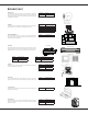
DRAIN KIT
An indoor/outdoor drain kit is available as an accessory
item. When a drain kit is to be installed, do so before
installing the wall sleeve in the wall. See the drain kit for
actual installation instructions.
SUBBASE, LEVELING LEGS, MAIN DUCT, AND
HYDRONIC HEAT KITS
Installation of these kits requires drilling of mounting
holes on both sides of the wall sleeve. The minimum
required clearance distance between the wall sleeve and
wall is shown in Table 1. If the distance between wall
sleeve and wall will be at or near the minimum clearance
distance, mount these kits on the sleeve before installing
the sleeve in the wall. The kit installation instructions are
included with the accessory kits.
1
6
1
/
1
6
"
4
1
0
m
m
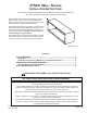
Wall Receptacle Within 58" From
Bottom Right Side Corner on
208/230 VAC Units Only
4
2
"
1
0
6
5
m
m
1
4
1
/
8
"
3
5
9
m
m
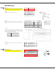
Figure 1 - Wall Sleeve Dimensions
1
If inside mounted then B = 1 1/2 inches (40 mm)
2
To achieve a flush fit between the hydronic front and the finished wall, Dimension “C” must be between 3” and
3 1/8”. If this dimension is more than 3 1/8” there will be a gap between the front and the wall. This gap could
permit occupant access to hydronic lines or other dangerous parts.
3
This dimension can be from 0” to 3-1/4”, but cannot exceed 3-1/4”. If this dimension exceeds 3-1/4”, the skirt
around the front will not reach the floor.
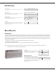
Table 1
KIT ACCESSORIES
4
2
1
/
4
"
1
0
7
5
m
m
M
i
n
i
m
u
m
1
6
1
/
4
"
4
1
5
m
m
M
i
n
i
m
u
m
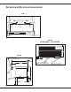
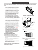
Finished Floor
Dimension "B"
in Table 1
Figure 2 - Minimum Wall Opening Dimensions
Top of Wall Sleeve
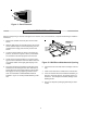
"A"
Minimum
"A"
Minimum
Internal
Adjacent
Wall
Internal
Adjacent
Wall
Outside
Wall
Allow Front Clearance (See Table 1)
Figure 3 - Minimum Unit Clearances
"C" in
Table 1
1/4"
6 mm
Minimum
"B" in
Table 1
Cabinet
Side
Outside
Wall
Room
Side
Carpet or
Finished Floor
Figure 4 - Minimum Interior and Exterior
Inches mm Inches mm Inches mm
Wall Sleeve Only 3750 0 0 0
Subbase Kit 3 75 3 1/4 85 2 3/4 70
Leveling Legs Kit 3 75 3 75 2 50
Duct Kit 3 75 0 0 2 3/8 35
Hydronic Heat Kit "A Series" 9 230
0 to 3 1/4
3
0 to 85
3
3
2
75
2
Hydronic Heat Kit "J Series" 6 150 0 0 2 1/2 65
Drain Kit 3 75
'0
1
'0
1
00
Hardwire Kit 3 75 1 1/4 30 0 0
OPTION
MINIMUM CLEARANCES AND PROJECTIONS
MINIMUM CLEARANCES MINIMUM PROJECTION
C (Figure 4)B (Figure 3)A (Figure 2)