Service Instructions PACKAGE TERMINAL AIR CONDITIONERS & HEAT PUMPS ` This manual is to be used by qualified HVAC technicians only. Goodman does not assume any responsibility for property damage or personal injury for improper service procedures done by an unqualified person. RS4200003 Rev.
INDEX PRODUCT IDENTIFICATION ........................................................................................................ 4 SPECIFICATIONS ......................................................................................................................... 5 PROPER INSTALLATION ........................................................................................................... 12 WALL SLEEVE INSTALLATION .................................................................................
IMPORTANT INFORMATION Pride and workmanship go into every product to provide our customers with quality products. It is possible, however, that during its lifetime a product may require service. Products should be serviced only by a qualified service technician who is familiar with the safety procedures required in the repair and who is equipped with the proper tools, parts, testing instruments and the appropriate service manual.
PRODUCT IDENTIFICATION NT E 12 A 35 A 3 * A Package Engineering Terminal Units Revision Model Type E - Cooler P - Heat Pump Voltage 3 = 230/208-1-60 4 = 265-1-60 Option Code Nominal Cooling Capacity 07: 7,000 Btuh 09: 9,000 Btuh 12: 12,000 Btuh 15: 15,000 Btuh A = Standard Model C = Seacoast Model Electric Heat 25 = 2.
SPECIFICATIONS COOLING DATA (COOLING with ELECTRIC HEAT) PTC073A**AA Voltage 1&3 Capacity (BUTH) PTC074A**AA PTC093A**AA PTC094A**AA PTC123A**AA PTC124A**AA PTC153A**AA PTC154A**AA 230/208 265 230/208 265 230/208 265 230/208 265 7,500/7,400 7,500 9,000/8,800 9,000 12,200/12,000 12,200 14,200/14,000 14,200 Amps 2.5/2.6 2.0 3.5/3.8 3.0 4.6/5.0 3.7 7.4/7.9 6.5 Watts 625/610 625 810/790 810 1,145/1,125 1,145 1,510/1,490 1,510 11.6 11.6 11.1 11.1 10.8 10.8 9.
SPECIFICATIONS HEATING PERFORMANCE - REVERSE CYCLE Heating Capacity Reverse Cycle PTH073A**AA 1&7 PTH074A**AA PTH094A**AA PTH123A**AA PTH124A**AA PTH153**AA PTH154A**AA Amps 2.6/3.0 2.2 2.6 4.5/5.1 3.9 5.0/5.6 4.1 Watts 575/565 575 770 1,020/1,000 1,020 1,350/1,320 1,350 BTUH5 6,800/6,700 6,800 8,500 11,200/11,100 11,200 13,400/13,100 13,400 3.3 3.3 3.2 3.1 3.1 2.9 2.
SPECIFICATIONS HEATING PERFORMANCE - REVERSE CYCLE Heating Capacity Reverse Cycle1&7 PTH073A**AB PTH073A**AC PTH074A**AB PTH074A**AC PTH093A**AB PTH093A**AC PTH094A**AB PTH094A**AC PTH123A**AB PTH123A**AC PTH124A**AB PTH124A**AC PTH153A**AB PTH153A**AC PTH154A**AB PTH154A**AC Amps 2.6/3.0 2.2 3.2/3.6 2.6 4.5/5.1 3.9 5.7/6.3 5.
SPECIFICATIONS COOLING DATA (COOLING with ELECTRIC HEAT) PTC073B***E PTC073B***G PTC073B***J PTC073B***K Voltage1&3 Capacity (BUTH) PTC074B***E PTC074B***G PTC074B***J PTC074B***K PTC093B***E PTC093B***G PTC093B***J PTC093B***K PTC094B***E PTC094B***G PTC094B***J PTC094B***K PTC123B***E PTC123B***G PTC123B***J PTC123B***K PTC124B***E PTC124B***G PTC124B***J PTC124B***K PTC153B***E PTC153B***G PTC153B***J PTC153B***K PTC154B***E PTC154B***G PTC154B***K PTC154B***J 230/208 265 230/208 265 230/208
SPECIFICATIONS HEATING PERFORMANCE - REVERSE CYCLE Heating Capacity Reverse Cycle1&7 Amps PTH074B***E PTH074B***G PTH074B***J PTH074B***K 6200 PTH073B***E PTH073B***G PTH073B***J PTH073B***K 6,200/6,000 PTH123B***E PTH123B***G PTH123B***J PTH123B***K 10,800/10,600 PTH094B***E PTH094B***G PTH094B***J PTH094B***K 8200 PTH093B***E PTH093B***G PTH093B***J PTH093B***K 8,200/8,000 PTH124B***E PTH124B***G PTH124B***J PTH124B***K 10800 PTH153B***E PTH153B***G PTH153B***J PTH153B***K 13,300/13,200 PTH154B***
SPECIFICATIONS COOLING DATA (ELECTRIC HEAT) NTE07A**A3A Voltage 1&3 Capacity (BUTH) NTE07A**A4A NTE09A**A3A NTE09A**A4A NTE12A**A3A NTE12A**A4A NTE15A**A3A NTE15A**A4A 230/208 265 230/208 265 230/208 265 230/208 265 7,100/6,900 7,100 9,100/8,900 9,100 11,900/11,700 11,900 13,700/13,500 13,700 Amps 2.8/3.0 2.3 3.7/3.8 3.0 4.9/5.3 4.3 6.3/6.9 5.9 Watts 655/640 655 830/810 830 1,165/1,145 1,165 1,540/1,515 1,540 10.8 10.8 11 11 10.2 10.2 8.9 8.9 4.0 3.6 5.
SPECIFICATIONS OPERATING VOLTAGES WARNING USE EXTREME CAUTION WHEN CHECKING HIGH VOLTAGE. Use a voltmeter, check the voltage at the outlet. The reading must be within the minimums and maximums shown below for the operating voltage. Operating Voltages Operating Voltage Minimum Voltage Maximum Voltage 230/208 197 253 265 238 291 NOTE: 1. All 265 volt models must use subbase or hard wire kit. 2. Minimum branch circuit ampacity ratings conform to the National Electric Code.
PROPER INSTALLATION WALL SLEEVE INSTALLATION Wood Frame Lintel WARNING HIGH VOLTAGE! DISCONNECT ALL POWER BEFORE SERVICING OR INSTALLING. MULTIPLE POWER SOURCES MAY BE PRESENT. FAILURE TO DO SO MAY CAUSE PROPERTY DAMAGE, PERSONAL INJURY OR DEATH. The wall sleeve must be installed before the air conditioner or heat pump chassis can be set in place. Read the instructions thoroughly before proceeding.
PROPER INSTALLATION Room Side Outside Wall "C" in Table 1 4 10 2 1/ Mi 75 m 4" nim m um Carpet or Finished Floor Cabinet Side 16 1/4" 415 mm Minimum "B" in Table 1 1/4" 6 mm Minimum Finished Floor Dimension "B" in Table 1 Minimum Interior and Exterior Projections Minimum Wall Opening Dimensions MINIMUM CLEARANCES AND PROJECTIONS Minimum Clearances Option A Minimum Projection B C in. mm in. mm in.
PROPER INSTALLATION Alternative Fastening Method (Field Supplied) 16 1/16" 410 mm Wood Screw Toggle Bolt Expansion Anchor Bolt Mounting Holes (Drilled by Installer) 10 42 65 " m m Wall Receptacle Within 58" From Bottom Right Side Corner on 208/230 VAC Units Only Plastic Anchor " 13 3/4 m 350 m Screws Attaching Wall Sleeve to Opening 6. Check the level of the wall sleeve and adjust if necessary.
PROPER INSTALLATION CHASSIS INSTALLATION 1. Remove the cabinet front from the chassis as described in Front Removal. per unit. The two screws must be removed before the front can be removed. Mounting Screws Location 2. Insert the chassis into the wall sleeve. Wall Sleeve Chassis Front Mounting Screws Slide Chassis In Outside Wall 3. Slide the chassis into the wall sleeve until the chassis flanges contact the front edge of the wall sleeve.
PROPER INSTALLATION NOTE: Heaterless units are shipped with an auxiliary data label on the front side of the mid-partition panel. If an electric heater kit is field installed, the installer must mark the appropriate box on the label to indicate the electric heater capacity. If no heater is installed, the box labeled “None” must be marked. Refer to the unit nameplate for over current protection data.
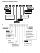
PROPER INSTALLATION SCHEMATICS BASED ON 1 STAGE COOL, 2 STAGE HEAT MECHANICAL THERMOSTATS Wiring Schematic for Remote Heat Pump A - B SERIES Wiring Schematic for Straight Cool Unit C - E SERIES O RS B B Y Y /W 1 W1 W2 W2 G G R R 1 4 P in C o n n e c to r C C o n t ro l B o a rd C o n n e c tio n s T h e rm o s ta t C o n n e c tio n s Wiring Schematic for Straight Cool Unit A - B SERIES R GL W2 Y/W1 B GH FD X1 O B Y W1 W2 G* EH IN LS FD1 FD2 TF(-)TF(+) C X1 AUXILIARY RC REMOTE THER
PROPER INSTALLATION REMOTE/STANDARD SWITCH (NOT USED ON NTE OR NTP MODELS) The figures below shows a wiring schematic for connecting the front desk switch to the unit. The remote/standard switch is used to change the control of the unit from the standard on board controls in the standard mode, to a remote wall mounted thermostat in the remote mode. For remote control operation refer to Remote Operation section. To set remote switch on the "G & K" board, see Configuration Settings.
PROPER INSTALLATION 1. Remove indoor ambient thermistor from plastic holder on indoor coil. Indoor Ambient Thermistor Plastic Holder Temperature Limiter The temperature limiting feature can reduce energy costs by controlling the maximum temperature available in heating and the minimum temperature available in cooling. While approximate temperature settings are shown below, actual room temperature will vary slightly.
PROPER INSTALLATION Diagnostic Light Temperature Limiting Screws The green diagnostic light located in the lower left hand corner of the touchpad and indicates operation warnings. This light usually indicates that either the filter or coils need cleaning. Please refer to the Maintenance and Cleaning section for the proper cleaning procedure. If this light is still on after cleaning, please refer to the Diagnostic & Status Report section for assistance. Additional Control Inputs Temperature Limiter 4.
PROPER INSTALLATION Use the following procedure to change the angle of the discharge air flow: Label 1. Remove the front cabinet (see Front Removal). 2. Position the front so that the backside is accessible. Vent Control Vent Door Shipping Screw Rotate the vent control lever to either open or close the damper. Vent Open 3. Remove the four nuts which secure the discharge air grille to the cabinet front.
PROPER INSTALLATION CONFIGURATION SETTINGS FOR G & K BOARDS The control can be configured to operate a wide range of options. The options listed below with the * are the factory default settings. If these are acceptable, then the unit does not require any additional configuration and is fully operable. To configure the unit, first select the configuration feature code setting and then an option code to change from the factory default setting. To enter configuration feature mode: 1.
PROPER INSTALLATION Feature Code Description Interface Usage C1 C2 Option Code Description 0* Unit is only controlled by the touchpad behind the door. rE Unit is both controlled by a wireless thermostat and/or the touchpad behind the door. L5 Unit is controlled by a wired thermostat only via on the low voltage terminals. Au* The fan only runs with the call for heating or cooling. On The fan runs continuously except in the OFF position.
MAINTENANCE NOTE: The compressor does not require maintenance. It is hermetically sealed, permanently lubricated. WARNING NOTE: Available accessory filter kits are FK10B (air intake filter - 10 per pack) and CFK10B (charcoal filter - 10 per pack). The charcoal filters will greatly improve the quality of the air by absorbing odors from tobacco smoke, mold, mildew, etc. Both filters are permanent and cleanable. Contact your sales person for details.
MAINTENANCE Basepan and Condenser Coil WARNING DO NOT USE COMMERCIAL GRADE COIL CLEANERS. SOME OF THESE CLEANERS MAY CONTAIN ETHYLENE DIAMINE TETRACETIC AICD (EDTA) WHICH CAN SHORTEN THE LIFE OF THE CONDENSER COIL. Vent - (Left Side Unit) Cabinet Front The cabinet front and discharge air grille can be cleaned with a water dampened cloth . Under no circumstances should hydrocarbon-based cleaners (e.g. acetone, benzene, naphtha gasoline, etc.) be used to clean the front or air grilles.
MAINTENANCE WARNING HIGH PRESSURE AND HIGH TEMPERATURE CLEANING IS NOT RECOMMENDED. DOING SO COULD DAMAGE THE ALUMINUM FIN STOCK AND ELECTRICAL COMPONENTS. CLEARANCE CHECK Clearances around the unit should also be checked to make sure that the intake air and discharge air paths have not become blocked or restricted. A minimum of eight inches clearance is needed from unit to furniture, beds, or other objects for proper operation.
OPERATIONS SEQUENCE OF OPERATION • Fan Advance/ Delay- The advance feature will allow the fan to start six seconds prior to the compressor starting in either cooling or heating mode. The delay will keep the fan running for thirty seconds after the compressor stops in either cooling or heating modes. • Remote Thermostats - Always use an approved thermostat supplied by the manufacturer. A wall thermostat that has not been approved by the manufacturer may not work correctly with this unit.
OPERATIONS • Sample Before Start - The SBS routine is used in the cooling mode. This routine runs the unit fan on low speed for up to 120 seconds. The sample fan is aborted if compressor demand is detected. To avoid unnecessary sampling the period between samples will be based on specific room conditions. The default sample before start period after a power up is 5 minutes. The period is corrected every time a sample run is completed without a compressor demand.
OPERATIONS the indoor discharge air temperature, Id; the outdoor coil temperature, OC; the outdoor ambient temperature, OA; and the spare probe temperature, IH. If any of the probes are not populated the display will show the corresponding failure code. Past Failure Log • If not in Diagnostic Status Report Mode, enter as instructed above and press the Fan Speed key twice. • If already in Diagnostic Status Report mode, press the Fan Speed key.
Refrigeration Sealed System OPERATIONS Process Strainer Capillary Tube Discharge Line Suction Line Condenser Evaporator Compressor Refrigeration Sealed System - Air Conditioner Capillary Tube Check Valve (Open) Process Strainer Capillary Tube Discharge Line Suction Line Condenser Evaporator Suction Line D i s c h a r g e L i n e Reversing Valve Compressor Refrigeration Sealed System - Heat Pump (Air Conditioning Mode) 30
Refrigeration Sealed System OPERATIONS Capillary Tube Check Valve (Closed) Process Strainer Capillary Tube Suction Line Discharge Line Condenser Evaporator Suction Line D i s c h a r g e L i n e Reversing Valve Compressor Refrigeration Sealed System - Heat Pump (Heat Pump Mode) 31
SERVICING REFRIGERATION SYSTEM SERVICE WARNING HIGH VOLTAGE! DISCONNECT ALL POWER BEFORE SERVICING OR INSTALLING. MULTIPLE POWER SOURCES MAY BE PRESENT. FAILURE TO DO SO MAY CAUSE PROPERTY DAMAGE, PERSONAL INJURY OR DEATH. from the truth. Oxygen from moisture plus normal compressor and motor heat reacts chemically with the refrigerant and oil to form corrosive hydrochloric and hydrofluoric acids.
SERVICING IMPORTANT NOTE: Effective July 1,1992. Before opening any refrigerant system it is the responsibility of the service technician to capture the refrigerant for safe disposal. This is the most important part of the entire service procedure. The life and efficiency of the equipment is dependent upon the thoroughness exercised by the serviceman when evacuating air (non-condensables) and moisture from the system.
SERVICING Cooling Performance Test Thermometers The following precautions are necessary in observing the thermometer readings in the cooling performance test. 1. Use two accurately calibrated refrigeration type thermometers or a thermocouple potentiometer. 2. Thermometers are affected by body heat or changes in air flow. Therefore, the thermometers must be secured in proper locations with masking tape, wire or other applicable retainers. 3.
SERVICING In column headed Outdoor Dry Bulb Temperature of the Power Consumption Chart find the 95°F value. Read to the right from the 95°F value and find the room wet bulb temperature (75°F). 1. Outside coil inlet D.B. temperature readings as described in Step A: 45°F. Read to the right front the 75°F W.B. value in the PTH15 column and note the minimum and maximum wattage of 1460 1575. 3. Inside coil inlet D.B. temperature reading as described in Step B: 75°F.
SERVICING COOLING WATTAGE - HEAT PUMPS Model Temperature Outside Coil Dry Bulb (ºF) 100 95 90 85 80 36 Room Wet Bulb (ºF) PTH073 PTH074 PTH093 PTH094 PTH123 PTH124 PTH153 PTH154 Total Wattage Input Total Wattage Input Total Wattage Input Total Wattage Input Total Wattage Input Total Wattage Input Total Wattage Input Total Wattage Input Min Max Min Max Min Max Min Max 85 625 698 805 885 1110 1205 1500 1615 80 630 700 810 890 1115 1210 1520 1635 75 630 700
SERVICING COOLING CHANGE OF TEMPERATURE - AIR CONDITIONERS Model PTC073 Temperature Outside Coil Dry Bulb (ºF) Room Wet Bulb (ºF) 85 90 85 80 75 70 Temperature Across Indoor Coil (ΔT) PTC074 PTC093 PTC094 PTC123 PTC124 PTC153 PTC154 Temperature Temperature Temperature Temperature Temperature Temperature Temperature Across Across Across Across Across Across Across Indoor Coil (ΔT) Indoor Coil (ΔT) Indoor Coil (ΔT) Indoor Coil (ΔT) Indoor Coil (ΔT) Indoor Coil (ΔT) Indoor Coil (ΔT) Min Max
SERVICING COOLING AMPERAGE CHART - AIR CONDITIONER M o del P T C 0 73 P T C 07 4 P T C 09 3 P T C 09 4 P T C 123 P T C 124 P T C 153 P T C 154 C o nd Inlet A ir T empe rature (ºF ) A mperage A mpera ge A mpera ge A mpe rage A mpe rage A mpe rage A mperage A mpera ge M in M ax M in M ax M in M ax M in M ax M in M ax M in M ax M in M ax M in M ax 100 2.8 3.0 2.3 2.5 3.5 3.9 2.7 2.9 4.8 5.4 4.0 4.4 6.4 7.1 5.8 6.4 95 2.6 2.9 2.2 2.4 3.3 3.7 2.5 2.
SERVICING HEATING CHANGE OF TEMPERATURE - HEAT PUMPS Model PTH073 PTH074 PTH093 PTH094 PTH123 PTH124 PTH153 PTH154 Temperature Across Indoor Coil (ΔT) Temperature Across Indoor Coil (ΔT) Temperature Across Indoor Coil (ΔT) Temperature Across Indoor Coil (ΔT) Temperature Across Indoor Coil (ΔT) Temperature Across Indoor Coil (ΔT) Temperature Across Indoor Coil (ΔT) Temperature Across Indoor Coil (ΔT) Max Temperature Outside Coil Dry Bulb (ºF) 50 45 40 35 Room Wet Bulb (ºF) Min Max M
SERVICING Past Failure Log DIGITAL BOARD DIAGNOSTICS If a failure is detected on the digital board, there will be a green light constantly lit up. This light is located under the OFF touch pad button. The board will need to be programmed in the Diagnostic Mode to determine failure code and procedures to follow to correct problem.
SERVICING DIAGNOSTIC CODES CODE F A I L U R E S L O C K O U T S W A R N I N G S STATUS FP Freeze Protection Engaged. The room tem perature m easured by the wireless rem ote therm ostat or indoor am bient therm istor active sensor falls below 40°F. Fd Front Desk switch is closed. All outputs are switched off.
SERVICING PTAC ANALYSIS CHART Power Failure Blown Fuse Loose Connection Shorted or Broken Wires Open Overload Faulty Thermostat Shorted or Open Capacitor Internal Overload Open Shorted or Grounded Compressor Compressor Stuck Open Control Circuit Low Voltage Faulty Evap or Cond.
SERVICING S-1 Checking Voltage the evaporator. 9. Pull heater assembly up and out of the chassis. WARNING LINE VOLTAGE NOW PRESENT. 10. Disconnect floodback protector. 11. If the unit has a Red Thermistor on the indoor coil follow steps 1-6 then steps 12 and 13. 12. Remove the access panel on the evaporator assembly. 1. Using a voltmeter, measure the voltage across terminals L1 and L2 of the outlet. 2. No reading - indicates open wiring, open fuse(s), no power or etc.
Checking Switchover Thermostat 5. All heater assembly components are now accessible. 1. With power off, remove the switchover thermostat leads from the circuit board. 2. Check, the switchover thermostat for continuity . Below 25° ±5°F the thermostat should read open. Above 60° + 6°F the thermostat should always read closed.
THERMISTOR RESISTANCE - TEMPERATURE CHARACTERISTIC Thermistor Resistance-Temperature Characteristic 180000 Resistance (ohms) 160000 140000 120000 100000 80000 60000 40000 20000 0 0 10 20 30 40 50 60 70 80 90 100 110 120 130 140 150 160 170 Temperature (deg F) 45
SERVICING S-15 Capacitor Check Attach Line Sel red wire to appropriate voltage terminal. XFRMR SELECT LOW COOL OFF OUTDOOR COIL INDOOR COIL INDOOR AIR Ohmmeter ON ON ON / OFF LED1 MASTER SWITCH STATUS Ohmmeter REV.
SERVICING 14. Pressing the tabs on the right side of the shroud separate the shroud from the outdoor coil. Voltmeter 15 Amp Fuse 15. Remove the two screw securing the outdoor coil to the base pan. 16. Carefully lift the outdoor coil over the basepan lip away from the fan wheel. Capacitor Ammeter 17. Push the shroud back toward the center partition panel. 18. Loosen the Allen screw securing the fan wheel clamp to the motor shaft. Remove the fan blade.
SERVICING Test Cord Connections WARNING TO PREVENT PROPERTY DAMAGE, PERSONAL INJURY OR DEATH DUE TO ELECTRICAL SHOCK, DO NOT CONNECT ELECTRICAL POWER TO THIS UNIT OR TO THE COMPRESSOR IF THE COMPRESSOR TERMINAL COVER HAS BEEN REMOVED OR IS NOT FIRMLY IN PLACE. L1 L2 Fuses Compressor Top Outlet If the test indicates shorted, grounded or open windings, see procedure for the next steps to be taken. Accumulator Terminals R S C Resistance Test 1.
SERVICING c. Low temperature difference across coil. d. Low amp draw at compressor. and the charge is correct. The compressor is faulty - replace the compressor. NOTE: THIS TEST CANNOT BE DONE IN THE HEATING MODE. S-116 Filter Drier Replacement 6. Clean the end of the capillary tube and insert into the tube, it may be necessary to crimp tubing around the capillary tube, being careful not to damage the capillary tube.
DISASSEMBLY If no voltage is registered to the coil, check the operation of the reversing relay and the continuity of the connecting wires. If voltage is registered at the coil, tap the valve body lightly while switching the system from HEATING to COOLING etc. If this fails to cause the valve to switch position, remove the coil connector cap and wiring and test the continuity of the valve coil. If the coil does not test continuous replace it. If the valve is inoperative, replace.
DISASSEMBLY 6. Remove the two screws securing the top screen to the evaporator assembly. (Be sure to slide the top of the screen between the top flange and chassis when reassembling.) Right Side Of Unit Control Panel 7. Remove screws on mid partition panel and shift out of the way. Power Cord Clamp 8. Remove the two screws securing the heater assembly to the evaporator. Incoming Power Opening Power Cord 9. Pull heater assembly up and out of the chassis. 5.
SCHEMATICS ! WARNING TO AVOID POSSIBLE ELECTRICAL SHOCK, PERSONAL INJURY, OR DEATH, DISCONNECT THE POWER BEFORE SERVICING. 1ST STAGE ANTICIPATOR CURRENT: .1 2ND STAGE ANTICIPATOR CURRENT: .
SCHEMATICS ! WARNING TO AVOID POSSIBLE ELECTRICAL SHOCK, PERSONAL INJURY, OR DEATH, DISCONNECT THE POWER BEFORE SERVICING.
SCHEMATICS ! WARNING TO AVOID POSSIBLE ELECTRICAL SHOCK, PERSONAL INJURY, OR DEATH, DISCONNECT THE POWER BEFORE SERVICING. 1ST STAGE ANTICIPATOR HEAT PUMP W/AUXILLARY CURRENT: .1 2ND STAGE ELECTRIC HEAT ANTICIPATOR CONNECT CONNECT CURRENT: .
SCHEMATICS ! WARNING TO AVOID POSSIBLE ELECTRICAL SHOCK, PERSONAL INJURY, OR DEATH, DISCONNECT THE POWER BEFORE SERVICING. 1ST STAGE ANTICIPATOR HEAT PUMP W/AUXILLARY CURRENT: .1 2ND STAGE ELECTRIC HEAT ANTICIPATOR CONNECT CONNECT CURRENT: .
SCHEMATICS ! WARNING TO AVOID POSSIBLE ELECTRICAL SHOCK, PERSONAL INJURY, OR DEATH, DISCONNECT THE POWER BEFORE SERVICING. 1ST STAGE ANTICIPATOR HEAT PUMP W/AUXILLARY CURRENT: .1 2ND STAGE ELECTRIC HEAT ANTICIPATOR CONNECT CONNECT CURRENT: .
SCHEMATICS ! WARNING TO AVOID POSSIBLE ELECTRICAL SHOCK, PERSONAL INJURY, OR DEATH, DISCONNECT THE POWER BEFORE SERVICING.
SCHEMATICS ! WARNING TO AVOID POSSIBLE ELECTRICAL SHOCK, PERSONAL INJURY, OR DEATH, DISCONNECT THE POWER BEFORE SERVICING. 1ST STAGE ANTICIPATOR CURRENT: .1 2ND STAGE ANTICIPATOR CURRENT: .
SCHEMATICS ! WARNING TO AVOID POSSIBLE ELECTRICAL SHOCK, PERSONAL INJURY, OR DEATH, DISCONNECT THE POWER BEFORE SERVICING. 1ST STAGE ANTICIPATOR HEAT PUMP W/AUXILLARY CURRENT: .1 2ND STAGE ELECTRIC HEAT ANTICIPATOR CONNECT CONNECT CURRENT: .
SCHEMATICS ! WARNING TO AVOID POSSIBLE ELECTRICAL SHOCK, PERSONAL INJURY, OR DEATH, DISCONNECT THE POWER BEFORE SERVICING. 1ST STAGE ANTICIPATOR HEAT PUMP W/AUXILLARY CURRENT: .1 2ND STAGE ELECTRIC HEAT ANTICIPATOR CONNECT CONNECT CURRENT: .
SCHEMATICS ! WARNING TO AVOID POSSIBLE ELECTRICAL SHOCK, PERSONAL INJURY, OR DEATH, DISCONNECT THE POWER BEFORE SERVICING. 1ST STAGE ANTICIPATOR HEAT PUMP W/AUXILLARY CURRENT: .1 2ND STAGE ELECTRIC HEAT ANTICIPATOR CONNECT CONNECT CURRENT: .
SCHEMATICS ! WARNING TO AVOID POSSIBLE ELECTRICAL SHOCK, PERSONAL INJURY, OR DEATH, DISCONNECT THE POWER BEFORE SERVICING. 1ST STAGE ANTICIPATOR HEAT PUMP W/AUXILLARY CURRENT: .1 2ND STAGE ELECTRIC HEAT ANTICIPATOR CONNECT CONNECT CURRENT: .
SCHEMATICS ! WARNING TO AVOID POSSIBLE ELECTRICAL SHOCK, PERSONAL INJURY, OR DEATH, DISCONNECT THE POWER BEFORE SERVICING. REMOTE THERMOSTAT OPERATION COOLING UNIT W/ELECTRIC HEAT FUNCTION CONNECT R TO: OFF ----- OFF FAN G FAN G, Y/W1 HEAT G, W2 OR G,B,Y/W1 ----G G, Y/W1 COOL * COOL CONNECT R TO: FUNCTION WIRING DIAGRAM 20319701 1ST STAGE ANTICIPATOR CURRENT: .1 2ND STAGE ANTICIPATOR CURRENT: .
SCHEMATICS ! WARNING TO AVOID POSSIBLE ELECTRICAL SHOCK, PERSONAL INJURY, OR DEATH, DISCONNECT THE POWER BEFORE SERVICING. 1ST STAGE ANTICIPATOR CURRENT: .1 2ND STAGE ANTICIPATOR CURRENT: .
SCHEMATICS ! WARNING TO AVOID POSSIBLE ELECTRICAL SHOCK, PERSONAL INJURY, OR DEATH, DISCONNECT THE POWER BEFORE SERVICING. 1ST STAGE ANTICIPATOR CURRENT: .1 2ND STAGE ANTICIPATOR CURRENT: .
SCHEMATICS ! WARNING TO AVOID POSSIBLE ELECTRICAL SHOCK, PERSONAL INJURY, OR DEATH, DISCONNECT THE POWER BEFORE SERVICING. 1ST STAGE ANTICIPATOR CURRENT: .1 2ND STAGE ANTICIPATOR CURRENT: .
SCHEMATICS ! WARNING TO AVOID POSSIBLE ELECTRICAL SHOCK, PERSONAL INJURY, OR DEATH, DISCONNECT THE POWER BEFORE SERVICING. 1ST STAGE ANTICIPATOR CURRENT: .1 2ND STAGE ANTICIPATOR CURRENT: .
SCHEMATICS ! WARNING TO AVOID POSSIBLE ELECTRICAL SHOCK, PERSONAL INJURY, OR DEATH, DISCONNECT THE POWER BEFORE SERVICING. 1ST STAGE ANTICIPATOR CURRENT: .1 2ND STAGE ANTICIPATOR CURRENT: .
SCHEMATICS ! WARNING TO AVOID POSSIBLE ELECTRICAL SHOCK, PERSONAL INJURY, OR DEATH, DISCONNECT THE POWER BEFORE SERVICING. 1ST STAGE ANTICIPATOR CURRENT: .1 2ND STAGE ANTICIPATOR CURRENT: .