
Instruction manual


Description
Control board installation procedures are described in detail
in these instructions. Read and follow these instructions
carefully before replacing the control board. Failure to do so
may result in control board damage.
Important Note:
Damage to the control board can occur from failure to
disconnect power supply or failure to set the master switch
(located on the control board) to OFF before removing the
low voltage terminal strip cover from an installed control
board. Damage to this board by not following these instruc-
tions is considered misuse and not covered under either the
standard unit warranty or any extended service contract.
Important Note:
All warranty replaced boards must be returned to the parts
source from which they were purchased to insure proper
warranty credit.
PTAC CONTROL BOARD KIT
RSKP0006
I
NSTALLATION
I
NSTRUCTIONS
IO-660A
November 2006
ATTENTION INSTALLING PERSONNEL
As a professional installer you have an obligation to know the product better than the customer. This
includes all safety precautions and related items.
Prior to actual installation, thoroughly familiarize yourself with this Instruction Manual. Pay special attention
to all safety warnings. Often during installation or repair it is possible to place yourself in a position which is
more hazardous than when the unit is in operation.
Remember, it is your responsibility to install the product safely and to know it well enough to be able to
instruct a customer in its safe use.
Safety is a matter of common sense...a matter of thinking before acting. Most dealers have a list of specific
good safety practices...follow them.
The precautions listed in this Installation Manual are intended as supplemental to existing practices.
However, if there is a direct conflict between existing practices and the content of this manual, the
precautions listed here take precedence.
RECOGNIZE THIS SYMBOL AS A SAFETY PRECAUTION.
Figure 1
Electrostatic Discharge (ESD) Precautions
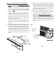
Before removing the new control board from the static wrap,
it is very important to discharge any static electricity. This
can be accomplished in two methods. Servicer can wear a
ground strap or by touching the metal chassis before replac-
ing the board.
Existing Control Board Removal Procedures
1. Disconnect power to the unit by unplugging the power
cord at the wall outlet or subbase, or disconnect power at
the fuse box or circuit breaker.
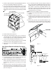
2. If the cabinet front is screwed to the chassis, remove the
1/4” screw (or screws) located behind the inlet grille. Pull
the inlet grille forward from the top of the grille to access
screw(s).
FRONT MOUNTING
HOLE
Printed in USA