
Instruction manual


2
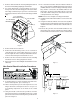
3. Remove cabinet front from chassis by tilting the bottom of
the front forward, lifting slightly up and forward.
4. If a remote thermostat or any low voltage accessory is
being used, remove the low voltage pin connector from the
low voltage terminal strip. If a previous version board is
being replaced remove wires from the low voltage terminal
strip.
1
2
3
O
N
PULL TO REMOVE
THERMOSTAT KNOB
Lift Off
PULL TO REMOVE
MODE SWITCH KNOB
ESCUTCHEON
SCREW (2)
SCREW
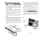
Figure 2
5. Remove knobs and escutcheon.
6. Remove the two mounting screws, one on each side of
control board cover. Some models may have a screw on
the lower right side of the control panel that will need to be
removed. Tilt control panel out and remove cover.
7. Remove the wires from the board in the unit, including
Thermistor Sensors if they plug into the board.
8. Remove the four screws holding the board and remove the
old board.
New Control Board Installation Procedures
9. If existing unit has a remote mounted “off board” trans-
former for board power, proceed to Step 13.
10. Lift the control panel up so the control panel is free of its
hinges. Orient the control panel so there is easy access
for mounting components to the inside of the control
panel.
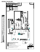
11. Using the two #8 screws that are provided, screw the
transformer that was provided with the kit to the control
panel in the transformer mounting holes provided in the
panel. See Figure 3.
12. The external transformer will come with the Black 37
wires connected to the LOAD terminal of the transformer
(LOAD terminals are the low voltage terminals) and the
Grey 22 wire connected to the COM terminal on the
transformer. The Grey 21 wire will need to be connected
to the 230 or 265 volt tap on the transformer. Place the
control panel back on its hinges.
NOTE: Refer to the serial plate for voltage information.
13. Install the new board and reinstall the screws removed in
step # 8.
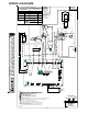
14. Using the insulated terminals connect the two (2) Black
37 wires from the Load terminals on the transformer to the
“24VAC Transformer” terminals on the control board. See
Figure 4.
15.Connect Grey 22 wire from the COM terminal on the
transformer to line 2 on the control board. Connect Grey
21 wire from the transformer to line 1 on the control board.
TRANSFORMER
Figure 3
GY22
BK37
BK37
LINE 1
HEATER 1
HEATER 2
LINE 2
COMPRESSOR
24VAC~TRANSFORMER
12VA CLASS 2 ONLY
GY21
TRANSFORMER
LINE
L
O
A
D
C
O
M
2
6
5
2
3
0
Figure 4