
Instruction manual


3
A3. Replace the heater panel, routing the yellow wire
around the right end of the heater panel and into the
control panel pulling snug to prevent the wire from
being entangled in the blower wheel or being visible
from above. Replace the two screws mounting the
heater panel to the evaporator coil.
A4. Replace the exhaust grille and two mounting screws.
A5. Connect the yellow wire using the plug-on connector
to the new board on the IDT (yellow) terminals.
B. If the existing Indoor Ambient Thermistor (with the
BLACK wires) was connected to the board by a plug-
on connector, reconnect it to the new board on the IAT
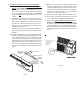
(black) terminals. If the existing Indoor Coil Ther-
mistor was soldered to the previous board, install the
new black thermistor per Figure 6 and connect as
above.
16. Thermistor Temperature Sensors Installation
A. It is recommended that the Indoor Discharge Ther-
mistor (with the YELLOW wires) be installed but it is
optional. If you chose not to install this sensor, the
green status light will remain illuminated continu-
ously. For status light functionality, the YELLOW
thermistor MUST be installed. Instructions are as
follows:
A1. Carefully cut and remove the gasket on the left and
right sides of discharge screen. Remove the two (2)
5/16” screws holding the indoor exhaust screen above
the indoor coil. Remove the indoor exhaust screen.
Remove the two (2) 1/4” screws connecting the heater
panel to the evaporator coil.
Remove the two (2) screws mounting the air baffle to
the top of the heater panel and remove and discard the
air baffle.
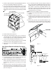
A2. Install the new air baffle. Route the yellow thermistor
probe from right to left through the wiring tube enclo-
sure. Mount the black tip of the yellow thermistor
probe in the plastic clip provided. Hold the plastic
clamp in place and secure the clamp to the left end of
heater panel using one of the original screws. Re-
place the screw on the right end of the air baffle being
careful not to damage the wiring insulation on the
probe.
YELLOW
THERMISTOR
PLASTIC CLAMP
CLAMP END OF
THERMISTOR
SECURELY
WIRE ENCLOSURE
ROUTE THERMISTOR
THROUGH TUBE ON
BLOWER EXTENSION
Figure 5
Clip is designed to be pushed
into the coil between
the aluminum fins
and attach over
two (2) screws.
Figure 6