
Instruction manual


5
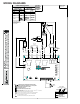
19. Power Vent/Power Door Units Only
(See Wiring Diagram Page 9)
Reconnect the wires across the top terminals of the
control board. Connect as follows:
Red 33 to Line 1
Brown 34 to heater 1
Brown 34 to Heater 2
Power cord (or black 18) to Line 2
Violet 12 to Compressor
Blue 4 to Fan high
Blue 15 and Blue 10 to Fan Low
19 from reversing valve to Rev. Valve
Connect the white 7 wire to the 230 or 265-volt terminal as
applicable using the piggyback terminal on the white 7
wire. Go to step 21.
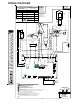
20. Reconnect the wires across the top terminals of the
control board. Connect as follows:
(See Wiring Diagram Page 8)
Red 33 to line 1
Brown 34 to heater 1
Brown 34 to heater 2
Power cord or black 18 to line 2
Violet 12 to compressor
Black 16 to Fan High
Red 17 to Fan Low
19 from reversing valve to Rev. Valve.
21. If a remote wired thermostat and an additional REK01B
escutcheon that states “THIS UNIT IS CONTROLLED BY
WALL MOUNTED THERMOSTAT” is used, the knob and
potentiometer will need to be removed. To remove the
knob, loosen the set screw on the side of the knob with
a flat screwdriver and pull knob from potentiometer shaft.
To remove the potentiometer, loosen the nut with a 10mm
driver and remove the nut and 2 washers. Pull the shaft
free of the panel. Reassemble potentiometer, washers,
nut and knob and store for future use. These will be
required if the unit is ever converted back to local controls
instead of wired thermostat operation.
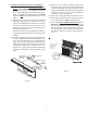
The control board cover is now ready to be installed. The
ribbon for the touch pad will need to be connected to the
control board. Take caution not to bend or fold the
ribbon (See Figure 9 for ribbon connection).
Install orange connector from the thermostat on the touch
pad to the IHD Terminals on control board, unless the
knob has been removed.
Ensure that no wires are pinched or caught between the
cover and the panel and then reinstall the screws removed
in Step 5.
22. If a remote thermostat or any low voltage accessory is
being used connect the low voltage pin connector to low
voltage terminal strip.
If replacing a previous version board you will need to use
the 18 pin connector supplied with the board for low
voltage accessories. Wires supplied with this kit have
terminal ends on the wires. Insert the terminal end into
the correctly labeled slot, push in and it will lock in place.
After loading pin connector use the wire nuts supplied
with the kit to wire nut the new wires onto the existing
wires supplied for low voltage accessories. See Figure 9
on page 5.
23. Set the master switch to ON. Restore electrical power
and verify unit functionality.
24. This control can be configured for several operational
features.
A. If the unit was being controlled by a wired wall
thermostat, the board will have to be configured to
allow the thermostat to operate the unit. To configure
for a wired wall thermostat, press and hold the FAN
SPEED button and press the COOL button twice. The
light in the bottom left hand corner below the OFF light
will blink twice to confirm that the configuration was
successful. Repeat step 24 if the light did not blink.
B. If the unit will be controlled by a wireless thermostat
(Goodman DS01A using DT01A antenna on the unit),
the board may have to be configured to allow the
wireless thermostat to operate the unit. To configure
for wireless operation, press and hold the FAN SPEED
button and press the HEAT button twice. The light in
the bottom left hand corner below the OFF light will
blink twice to confirm that the configuration was
successful. Repeat step 24 if the light did not blink.
C. If constant fan is desired, the unit will need to be
configured by pressing and holding the HEAT button
and pressing the OFF button twice. To revert to auto/
cyclic fan operation, press and hold the COOL button
and press the OFF button twice.
D. Other configuration items exist, but can only be
accessed over the wireless antenna to a wireless site
platform (Goodman DP01A).
E. To reset all the configuration items back to the factory
defaults, turn the master switch off for 10 seconds,
and then hold the HEAT and COOL button while
turning the master switch back on.
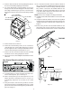
25. Replace the front in reverse order as removed in Steps 2
and 3.