
Owner`s manual


4
• Ensure a minimum clearance of three (3) inches around
the unit for adequate airflow.
• Ensure the condensate drain is unobstructed and leak-
free.
NOTE: The wall sleeve has a 3/4 NPT nipple located in the
bottom for connection to the drain. A trap may be required
in the condensate drain line to prevent sewer gas from
escaping into the room.
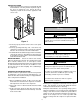
SLEEVE INSTALLATION
Refer to installation instructions packed with wall sleeve to
assemble and mount it in the wall. Ensure that the construc-
tion debris guard is removed and that the bottom of the wall
sleeve is pitched 1/2 bubble toward the outside of the
building. This angle forces any rain water that might enter
to drain to the outside. Also inspect the bottom of the wall
sleeve pan and drain. They should be clear of obstruction
and operational.
Figure 2
ARCHITECTURAL GRILLE
This model requires an Architectural Grille. It must be
installed before installing the unit.
The architectural grille directs air flow for proper unit opera-
tion and protects the outdoor coil. Refer to the Installation
Instructions supplied with the architectural outdoor grille kit
for a complete description of the installation procedure.
Installation Instructions
To ensure that the unit operates safely and efficiently, it
must be installed, operated and maintained according to
these installation and operating instructions and all local
codes and ordinances or, in their absence, with the latest
edition of the National Electric Code. The proper installation
of this unit is described in the following sections. Following
the steps in the order presented should ensure proper
installation.
PRE-INSTALLATION CONSIDERATIONS
• Ensure that properly sized duct work is in place to mate
to the supply connection on the SPVU.
• Remove the two clips holding the unit to the shipping
pallet and remove unit from the shipping pallet.
• Before setting unit into closet, remove upper side
access panels and inspect the evaporator blower to
ensure that the wheel turns freely without rubbing on
the housing.
• Remove the styrofoam shipping block supporting the
blower assembly and replace the upper access panels.
• Remove front access panel and remove packing and
quick disconnect plug.
• Check all electrical connections and ensure the con-
denser fan turns freely. Note nameplate voltage,
amperage and fuse size for proper power supply.
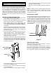
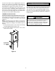
• If ducted return air is required, bend out the intake air
flanges 90° away from the unit.
• A outdoor air vent panel is located on the lower left side
unit. Remove one screw and rotate the plate to expose
the desired amount of vent opening. Tighten the
remaining screw. Place the removed screw in the open
screw hole on the unit.
Figure 1
• Ensure that the wall sleeve is installed squarely and is
secure before installing the unit.
• Ensure the sleeve seal on the wall sleeve is properly
secured and aligned.
• Ensure the architectural or outdoor grille is installed.
Ducted Return
Air Flanges
Outdoor Air
Vent
1/2 Bubble Tilt