
Owner`s manual


6
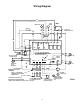
The unit comes with a factory-supplied quick disconnect,
however, the contractor is responsible for providing over
current protection on the branch circuit. Refer to the unit
wiring diagram for single point electrical connection.
These units are provided with a Class 2 transformer for 24
volt control circuits. Should any add-on equipment also
have a Class 2 transformer furnished, care must be taken
to prevent interconnecting outputs of the two transformers
by using a thermostat with isolating contacts.
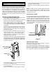
THERMOSTAT INSTALLATION
Install a factory approved or equivalent thermostat accord-
ing to directions furnished with the thermostat. The thermo-
stat should be located on an inside wall where it cannot be
affected by drafts, sunlight or any other heat producing
appliances.
NOTE: Heat Pump units operate with the reversing valve
energized in the HEATING mode. The thermostat must be
wired or configured accordingly or the unit will not operate
properly.
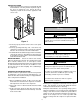
1. Connect thermostat wires to the thermostat following
the wiring diagram attached to the unit.
2. Connect low voltage thermostat wires from remote
thermostat to the unit.
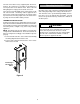
Figure 6
Operating Instructions
Operation of the unit is automatic and will provide heating
and cooling depending on the setting of the thermostat.
This unit must not be operated during building construc-
tions due to excessive airborne dust and debris. The unit
must not be operated under any circumstances without an
air filter in place.
WARNING
To prevent death or personal injury due to electrical
shock, turn off power at the fuse box or circuit
breaker before servicing the unit. Line voltage will be
present at the control board, terminals L1 and L2,
whenever power is applied to the unit.
Low Voltage
Thermostat
Wires