INSTALLATION AND OPERATION INSTRUCTIONS FOR BI-40-DEEP-XT BI-50-DEEP-XT BI-60-DEEP-XT BI-72-DEEP-XT BI-88-DEEP-XT SAFETY INFORMATION WARNING If the information in these instructions are not followed exactly, a fire or explosion may result causing property damage, personal injury or loss of life. Do not store or use gasoline or other flammable vapors and liquids in the vicinity of this or any other appliance. INSTALLER: LEAVE THIS MANUAL WITH THE APPLIANCE.
TABLE OF CONTENTS Please read and carefully follow all of the instruction found in this manual. Please pay special attention to the safety instructions provided in this manual. The instructions included here will assure that you have many years of dependable and enjoyable service from your Amantii product. IMPORTANT INSTRUCTIONS....................................................................................................................................3 UNPACKING AND TESTING APPLIANCE ...............
IMPORTANT INSTRUCTIONS 1. Read all instructions before installing or using this heater. 2. Keep combustible materials, such as furniture, pillows, bedding, papers, clothes and curtains at least 3 feet from the front of the heater; keep them away from sides and rear as well. 3. Always unplug heater when it’s not in use. 4. Do not operate the fireplace if it has a damaged cord or plug, after it has malfunctioned, or if the unit has been dropped or damaged in any way. 5.
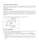
UNPACKING AND TESTING APPLIANCE Carefully remove the appliance from the box. Prior to installing the appliance, test to make sure the appliance operates properly by plugging the power supply cord into a conveniently located 120 Volt grounded outlet. GROUNDING APPLIANCE This appliance is for use on 120 Volts. The cord has a plug as shown in (A). An adapter as shown in (C) is available for connecting three-blade grounding type plugs to two-slot receptacles.
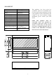
BI-40-DEEP-XT Description Voltage Watts NO HEATER MOTOR HEATER Appliance Width Appliance Height Appliance Depth Gross Weight Plug Location Cord Length Rough Wall Opening Size BTU This appliance has been tested in accordance with the UL Standard 2021 for fixed and location dedicated electric room appliances in the United States and Canada. If you need assistance during installation, please contact your local dealer. Built-in Appliance 120V AC 60Hz 1500W Max 25W 19W 38 5/8” or 98.
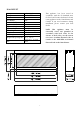
BI-50-DEEP-XT Model Number Voltage Watts NO HEATER MOTOR HEATER Appliance Width Appliance Height Appliance Depth Gross Weight Plug Location Cord Length Rough Wall Opening Size BTU This appliance has been tested in accordance with the UL Standard 2021 for fixed and location dedicated electric room appliances in the United States and Canada. If you need assistance during installation, please contact your local dealer. Built-in Appliance 120V AC 60Hz 1500W Max 25W 19W 48 5/8” or 123.
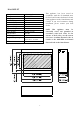
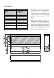
BI-60-DEEP-XT Description Voltage Watts NO HEATER MOTOR HEATER Appliance Width Appliance Height Appliance Depth Gross Weight Plug Location Cord Length Rough Wall Opening Size BTU Built-in Appliance 120V AC 60Hz 1500W Max 25W 19W 58 5/8” or 148.5 cm 29 1/2” or 75 cm 12 5/8” or 32.2 cm 127.6lbs or 58kg Left side 70 7/8” or 180 cm 60”× 30“ or 152.4 cm× 76.
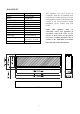
BI-72-DEEP-XT Description Voltage Watts NO HEATER MOTOR HEATER Appliance Width Appliance Height Appliance Depth Gross Weight Plug Location Cord Length Rough Wall Opening Size BTU This appliance has been tested in accordance with the UL Standard 2021 for fixed and location dedicated electric room appliances in the United States and Canada. If you need assistance during installation, please contact your local dealer. Built-in Appliance 120V AC 60Hz 1500W Max 25W 19W 72 1/8” or 183.
BI-88-DEEP-XT Description Voltage Watts NO HEATER MOTOR HEATER Appliance Width Appliance Height Appliance Depth Gross Weight Plug Location Cord Length Rough Wall Opening Size BTU This appliance has been tested in accordance with the UL Standard 2021 for fixed and location dedicated electric room appliances in the United States and Canada. If you need assistance during installation, please contact your local dealer. Built-in Appliance 120V AC 60Hz 1500W Max 25W 19W 88 5/8” or 225.
SAFETY DRILL SCREW AREA There is a safety drill screw area as show below. Please make sure that the fix screws are in this area. Sa fe ty d rill s cre w a re a (Da rk a re a ) T h e m a n u a l c o n tro l p a d p o s itio n HARD- WIRE INSTALLATION Turn off the appliance completely and let cool before servicing. Only a qualified service person should service and repair this electric appliance.
2. Attach the wiring to the junction block. Please make sure the live wire goes into the “L”, the neutral wire into “N” and the ground wire into “G”. 3. Put the plate back and screw back. FOR BATHROOM USE If this unit is installed in a bathroom it must be protected by a GIF receptacle or circuit. If receptacle is used it must be readily accessible.
OUTDOOR INSTALLATIONS The BI-DEEP-XT series electric fireplaces are suitable for installation in outdoor areas protected from direct water impingement. In addition to maintaining the listed mantel and combustibles clearances, a rain protection overhang factor of 1/2 shall be constructed to the front and to each side of the installed appliance. See illustration below. All wiring connections to line power shall be in accordance with local building code requirements.
INSTALLATION The BI-DEEP-XT models are designed to be built-in. These units allow for the finishing material (drywall, stone, tile, etc) to be built right down to the glass edge. However, that application is not always desirable or available so the surround could be used as an alternate finish option. Important note: The optional surround is not firmly attached and can be removed from the unit by simply pulling it off. It is recommended that two people remove the surround.
2. Remove the framing plates from the unit framing plate 3.
4. Bend up the framing plates. 5. Put the unit into the opening.
6. Drive the mounting screws into the framing plates on the unit and the wall studs. framing plate 7. After checking that the fireplace operates properly, cover the glass panel with protective plastic bag and install plywood or drywall. IMPORTANT NOTE: IF YOU WANT TO USE THE SUPPLIED SURROUND the thickness of the wall finish can only be 1”.
8. Decorate the plywood or drywall with glazed tile, wallpaper, etc. Fireplace 9. Put back the trim that you’ve removed from the unit at STEP 1.
MEDIA OPTIONS The BI-40-DEEP-XT is shipped with 1 set of FI-109-DIAMOND, BI-50-DEEP-XT and BI-60-DEEP-XT are shipped with 2 sets of FI-109-DIAMOND, BI-72-DEEP-XT and BI-88-DEEO-XT are shipped with 3 sets of FI-109-DIAMOND. FI-109-DIAMOND 3 glass nuggets, 1 bag of clear, 1 bag of small clear, 1 bag of clear diamond and 1 bag of blue diamond.
FIRE GLASS MEDIA-LOG INSTALLATION 1. Take off the front clear glass. There is a bracket that holds the front glass as shows below. Unscrew the screw to take off the bracket. Turn around the bracket and insert it into the gap to hook and pull out the glass. 2. Install the fire glass media. Pour the fire glass media into the tray as shows below. Feel free to use any combination of fire glass media that you find most appealing. IMPORTANT: GLASS IS VERY SHARP - PLEASE WEAR PROTECTIVE GLOVES 3.
OPERATION The fireplace can be operated either by the switches located on the left bottom of the fireplace unit or by supplied remote control. Plug the fireplace into a 15 Amp wall socket. MANUAL OPERATION 1. The main power ON/OFF switch in position O, the fireplace is OFF. 2. When main power ON/OFF switch is at position I, the fireplace is ready to use. 3. Press the button repeatedly to set the heater to desired heat setting. The heater indicator LED will glow which shows the current heater settings.
REMOTE CONTROL OPERATION For remote to function make sure the heater is plugged in and main power switch located on the bottom left hand side is at position I. When operating the remote make sure you point the remote to the centre of the fireplace and make sure each time you press the button the buzzer inside the unit will beep once. It takes some time for the receiver to respond to the transmitter. Do not PRESS the buttons more than once within two seconds for correct operation.
INSTALLING WALL THERMOSTAT WALL THERMOSTAT WIRING DIAGRAMS Wire the wall thermostat prior to installing the fireplace. WALL THERMOSTAT WIRING(24 VAC) Install Wall Thermostat per instructions provided with kit and per the following information: 1. Turn off circuit breaker. 2. Remove cover plate located on the left side of appliance. 3. Pull the wire out and cut the inside thermostat. Connect the wires to the wall thermostat as shown below. Follow instructions provided with wall switch kit.
REPLACEMENT PARTS This list contains replacement parts DESCRIPTION NO. BI-40-DEEP-XT BI-50-DEEP-XT BI-60-DEEP-XT BI-72-DEEP-XT BI-88-DEEP-XT 1 602030C 602030C 602030C 602030C 602030C BLOWER AND QTY.
EXPLODED VIEW 24
TROUBLE SHOOTING PROBLEM POSSIBLE CAUSE Dim or no flame Flame LED’s are burnt out Ember bed is not glowing or dimming Appliance turns off and will not turn on Appliance will not come on when switch is flipped to ON SOLUTION Inspect the LED’s and replace them if necessary. Ember LED’s are burnt out Inspect the ember bed LED’s and replace them if necessary.
SERVICE HISTORY This heater must be serviced annually depending on usage.