AMARI UE Simbox User guide
No Title Version: 2020-08-21
i Table of Contents 1 Introduction . . . . . . . . . . . . . . . . . . . . . . . . . . . . . . . . . . . . . . . . . . . . . . . . . . . . 1 2 Hardware setup . . . . . . . . . . . . . . . . . . . . . . . . . . . . . . . . . . . . . . . . . . . . . . . . 2 2.1 2.2 3 Connect your Simbox to the local network . . . . . . . . . . . . . . . . . . . . . . . . . . . . . . . . . . . . . . . . . . 8 Login . . . . . . . . . . . . . . . . . . . . . . . . . . . . . . . . . . . . . . . . . . . . . . . . . . . . . .
ii 6.3 7 6.2.5 Simulations tab . . . . . . . . . . . . . . . . . . . . . . . . . . . . . . . . . . . . . . . . . . . . . . . . . . . . . . . . . . . . . . 19 Export scenario . . . . . . . . . . . . . . . . . . . . . . . . . . . . . . . . . . . . . . . . . . . . . . . . . . . . . . . . . . . . . . . . . . . 21 Run UE scenarios with WebGui . . . . . . . . . . . . . . . . . . . . . . . . . . . . . 22 7.1 UE simulator tab . . . . . . . . . . . . . . . . . . . . . . . . . . . . . . . . . . . . . . . . . . .
iii 14 Troubleshooting . . . . . . . . . . . . . . . . . . . . . . . . . . . . . . . . . . . . . . . . . . . . . . 44 14.1 14.2 14.3 14.4 14.5 14.6 No SIB found . . . . . . . . . . . . . . . . . . . . . . . . . . . . . . . . . . . . . . . . . . . . . . . . . . . . . . . . . . . . . . . . . . . . 44 SIB found but attach fails . . . . . . . . . . . . . . . . . . . . . . . . . . . . . . . . . . . . . . . . . . . . . . . . . . . . . . . 44 Downlink peak throughput not achieved . . . . . . . . . . . . . . .
1 1 Introduction Amari UE Simbox is a UE simulator acting as a 3GPP compliant LTE and 5G NR UE (in NSA mode). It can simulate up to 1000 UEs sharing the same spectrum with different types of traffic within multiple cells. It is also supporting NB-IoT and LTE-M. The offer is completed by an integrated IP simulation package for reproducible test results. The UE Simbox is a turnkey solution running on Fedora 30 operating system.
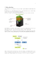
2 2 Hardware setup 2.1 Power supply Plug the external power cable provided with the Simbox in the AC-in Connector and place the toggle switch located in the rear panel on position "1", then press the Power on button on the top of the front panel to turn the system on. The led will light up blue once Simbox is powered ON . Power adapter specifications: Input: 100~240 V AC, 50~60 Hz 2.
Chapter 2: Hardware setup 3 • When RF cables are used, cabling must follow the instruction provided in the following sections. TX and RX gains must be adjusted accordingly. See [TX:RX gain setting], page 13, for more details Note: When using RF combiners, unused ports of the combiners must be terminated with RF terminator or absorber especially when using frequency above 2.5Ghz. Otherwise big insertionlosses may happen and downgrade the RF performances. 2.2.
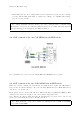
Chapter 2: Hardware setup 4 2.2.3 RF connection for one Cell MIMO 2x2 in TDD mode In TDD mode, as both TX and RX are sent on the same channel, only TX1 port is needed for the main antenna and RX2 for the diversity/MIMO antenna. However, with Amarisoft SDR card, it is possible to force the DL signal reception on RX port and Uplink signal transmission on TX port when rx_antenna: "rx" is set in the RF driver configuration file.
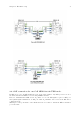
Chapter 2: Hardware setup 5 When rx_antenna: "rx" is set, RF connection is the same as for FDD. 2.2.4 RF connection for two Cells MIMO 2x2 in TDD mode As for FDD, in the picture below each eNodeB cell uses a different antenna port (RF#1 and RF#2). This configuration can be used for 2 neighbor cells or for a Carrier Aggregation test. When both cells are using the same eNodeB antenna port, please refer to second picture (one eNodeB antenna port) for the RF connection.
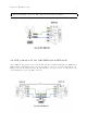
Chapter 2: Hardware setup 6 When rx_antenna: "rx" is set, RF connection is the same as for FDD. See section 2.2.3 for more details about rx_antenna: "rx" 2.2.5 RF connection for one Cell MIMO 4x4 in FDD mode In the case of MIMO 4x4, two SDR cards are required on the UE simulator side. Both SDR cards are combined in order to provide four TX and RX antenna ports.
Chapter 2: Hardware setup 7 2.2.6 RF connection for one Cell MIMO 4x4 in TDD mode As for FDD, two SDR cards are required on the UE simulator side. Both SDR cards are combined in order to provide four TX and RX antenna ports.
8 3 Connection to AMARI UE Simbox The AMARI UE Simbox does not have a built-in graphical card however you can remotely connect to the callbox by using one of the Ethernet ports. 3.1 Connect your Simbox to the local network The AMARI UE Simbox has two 1Gb Ethernet ports The first one (on the top) is configured with a static IP address 192.168.1.80. The second one is configured in DHCP mode and will get automatically an IP address within the range defined on your router.
9 AuthUserFile /etc/httpd/.htpasswd Require valid-user To add a user and its password, type the following command: htpasswd -c /etc/httpd/.
10 4 LTE service The UE Simbox is configured to provide an automatic LTE service. At each reboot of the PC, LTE UE service is turned on automatically. The default config is : - One LTE cat12 UE configured to camp on LTE cell Band7 (EARFCN 3350) SISO 5mhz bandwitdh. 4.1 Manage LTE automatic service 4.1.1 Status You can check the LTE service status this way: service lte status The command will return "active (running)" status if service is running 4.1.
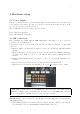
11 5 Initial setting 5.1 Selection of configuration file The default file used by LTE automatic service is ue.cfg (available under /root/ue/config directory). This files aims to configure the UE simulator parameters such as UE category, EARFCN, IMSI and others. To change the UE configuration, update this file and restart the LTE service with service lte restart command. Note: Some examples of configuration file (ue-nbiot.cfg, ue-catm1.cfg) are provided in Amarisoft releases as a starting point.
Chapter 5: Initial setting multi_ue: true, cells: [{ rf_port: 1, bandwidth: 20, dl_earfcn: 3350, n_antenna_dl: 1, n_antenna_ul: 1, }], }], 5.3.2 Example : 2 LTE cells from same eNodeB The example below represents a scenario with 2 cells from same eNodeB (synchonized) cell_groups: [{ group_type: "lte", multi_ue: true, cells: [{ rf_port: 0, bandwidth: 20, dl_earfcn: 6300, n_antenna_dl: 1, n_antenna_ul: 1, }, { rf_port: 1, bandwidth: 20, dl_earfcn: 3350, n_antenna_dl: 1, n_antenna_ul: 1, }, ] } ], 5.3.
Chapter 5: Initial setting 13 bandwidth: 20, dl_nr_arfcn: 632628, ssb_nr_arfcn: 632256, subcarrier_spacing: 30, n_antenna_dl: 1, n_antenna_ul: 1, }], }], 5.4 TX/RX gain setting TX and RX gain values must be fine tuned depending on your setup (conducted vs wireless conditions, physical attenuator used, combiner/divider, etc..) as dynamic power control is not handled at UE side (excepted if channel simulation mode is enabled) . TX and RX gain values are /root/ue/config/rf driver directory. look at ue.
Chapter 5: Initial setting 14 We recommend to use the automatic mode. However, if UEs encounter difficulties to synchronize with eNodeB signal you may have to adjust manually the timing advance. See [SIB found but attach fails], page 44, for more details. 5.6 Reload config files Once UE configuration is completed, you can restart your service to take these modifications into account with command lte service restart, and switch to LTE screen using screen -x lte command.
15 6 Create scenario using WebGui Once your UE simulator has been started and has decoded eNodeB system information (Cell 0: SIB found message is displayed) you can start using it to create devices, generate end to end traffic and simulate different channel conditions in order to test your eNodeB and Core network. These scenarios can be generated automatically using the WebGui as described below.
Chapter 6: Create scenario using WebGui 16 Once the server client is created and get connected to the LTE UE service, a new window will appear where logging level per layer can be set For more details about logging configuration, see ltewww.
Chapter 6: Create scenario using WebGui 17 • Then click on Add button. A new scenario named "New scenario" appears now in the main panel • Select New scenario to display the scenario panel on the right side. • Define a name for this scenario and configure parameters for all tabs as described below. 6.2.1 Create UEs tab Count Number of UE to create. If set to 0, the scenario shall only be applied to an already created UE. IMSI IMSI of each UE.
Chapter 6: Create scenario using WebGui 18 Sim mode: Uplink and downlink traffic flow of each UE is managed by an embedded traffic generator called "lte simserver" running on EPC side. No logical TUN interface is created per UE. TUN mode: Create a linux TUN interface per PDN for each UE. This allows to communicate with each UE independently through their network namespaces. Lte simserver is not required in that case. Iperf command can be used for generating or receiving IP traffic as instance.
Chapter 6: Create scenario using WebGui 19 Max simultaneous connected UE Maximum number of simultaneously connected UE. Simulation will avoid any power on until this limit is reached, in other words, next power on will occur after new power off. Power on duration Duration in seconds of power on period. UE will remain powered on during this time and them will power off, allowing a new UE to connect. Power off duration Minimum duration in seconds of power off period.
Chapter 6: Create scenario using WebGui 20 Once IP traffic selection has been done , additional parameters can be configured: Name Name of simulation Probability Between 0 and 1. When scenario is running, probability that a UE instance runs the simulation depends on probability (1 = 100% probablity, 0 means no chance, 0.5 means one out of two) . APN Allow to request a specific Access Point Name in the PDN connectivity request. The APN name defined here must be declared previously in the PDN tab.
Chapter 6: Create scenario using WebGui 21 6.3 Export scenario Once a scenario has been created, it’s possible to export it. In the center panel, the Export button generates a json config file that you can directly integrate in your UE configuration file for running it through command line instead of using the WebGUI. It also generates a MME config file that can be loaded on Amarisoft EPC to fill automatically the ue db of MME component.
22 7 Run UE scenarios with WebGui Once scenario have been created (as described in section above), you can now run them to test your eNodeB and EPC. In the center panel, select the scenario and click on run button Once started, two tabs UE simulator and UE simulator:scenarioName can be used to monitor the UE status, visualize chart and trigger manual actions 7.1 UE simulator tab When selecting simulator UE tab, several panels are displayed. 7.1.
Chapter 7: Run UE scenarios with WebGui 7.2 Scenario example • First create a scenario in UE scenario tab and call it My first test. • Select Simulations tab and add ICMP ping: • Click on Apply changes • Go to UE Simulator tab. • Click on red icon to power on UE and right click on UE: • Select My first test. A new tab is created to follow scenario.
Chapter 7: Run UE scenarios with WebGui 24 7.3 Executing scenario tab Following buttons are available: • Reset will flush logs • Retry will start scenario again • Stop will stop current scenario • Export will export in a CSV file scenario results 7.4 Example Let’s try the following exercise: • 100 UE have to be connected simultaneously. • 20 UE will connect every second. • Each UE will stay connected 10s • Each UE can’t be powered on less than 10s • Scenario will last 1 minute.
Chapter 7: Run UE scenarios with WebGui 25 So what can we do ? We can reduce power off duration but this will imply all UE will stay disconnected 0s ! And we can increase the amount of UE to have a constant pool of disconnected UE. Let’s do this: Then we can add our scripts: With this configuration, HTTP transfer will last 6s. As power on duration is 10s, it means HTTP transfer will start 2s after power on and will stop 2s before power off.
26 Take a look at URL: http://192.1.168.4.1:8080/data?size=10000 This URL will be interpreted by ltesim_server embedded HTTP server as a transfer of 10000 byte(s). Note that ltesim_server must be started with HTTP server enabled: sudo ./ltesim_server -a 192.168.4.
27 8 Create scenario without WebGui In order to ease automation, UE scenario can be directly defined in the ue.cfg file and run automatically when lte service is started. The exhaustive list of parameters that can be used are described in lteue.pdf documentation, chapter 7.3.
Chapter 8: Create scenario without WebGui 28 8.2.
Chapter 8: Create scenario without WebGui 29 "as_release": 8, "sim_events": [ { "start_time": 0, "event": "power_on" }, { "start_time": 5, "end_time": 305, "dst_addr": "192.168.3.
Chapter 8: Create scenario without WebGui 30 ue_list: [ { as_release: 8, ue_category: 4, imsi: "001010000000200", K: "00112233445566778899aabbccddeeff", /* Enable it to create a TUN interface for each UE PDN */ tun_setup_script: "ue-ifup", sim_events: [ { event: "power_on", start_time: 5, }, { "apn": "ims", "pdn_type": "ipv4v6", "start_time": 10, "event": "pdn_connect" }, { "start_time": 15, "event": "ext_app", "prog": "ext_app.sh", "args": ["iperf -c 192.168.4.
31 9 Downlink and Uplink transfer using iperf For running Downlink and Uplink test, iperf can be used on both sides: Core network and LTE UE simulator. However, when several instances of UE are used, network namespace (netns) is required at UE side. 9.1 Introducing Linux Network Namespaces A network namespace is logically another copy of the network stack, with its own routes, firewall rules, and network devices.
32 • On UE side, in linux shell, type ip netns list to list all network namespaces [root@localhost ~]# ip netns list ue2 ue1 • Select the targeted UE and execute the iperf command within its namespace Example: ip netns exec ue1 iperf -s -u -i 1 Note: any command can be run in the namespace, such as ping, ifconfig, etc..
33 10 NB-IOT devices 10.1 Stand alone cell When using standalone NB-IOT cell, only dl earfcn has to be set in ue.cfg file. The ul earfcn is automatically deduced Note : If Uplink Downlink spacing doesn’t follow standard values, ul earfcn must be set as well 10.2 Guard band and in band cell In in-band and guard band modes, RB used for NB-IOT in uplink and downlink are configured by the network. Uplink EARFCN and frequency offset values used are broadcasted via SIB2.
34 11 Channel simulator The LTE UE simulator embeds a channel simulator that can be used to alter UE measurements and simulate different radio conditions. The main parameter to activate the channel simulation is: channel_sim If set to "true", the UE channel simulator is enabled. Note: Channel simulator is only available in multi UE mode (multi ue = true).
Chapter 11: Channel simulator 35 11.2 UE parameters When the UE channel simulator is enabled (channel_sim = true), the following UE parameters must be provided (see lteue.pdf file for more details): • position • initial radius • speed • direction • noise spd • channel Those parameters can be set manually in the ue.cg file or configured automatically with the WebGui as described below. Scenario creation through WebGui is the easiest way to simulate noise and mobility.
Chapter 11: Channel simulator • Min distance = 0 • Max distance = 20 • Speed = 5 • Noise spectral density in dBm/Hz= -174 This generates the following ue list parameters : ue_list: [ { "ue_id": 1, "imsi": "001010123456789", "imeisv": "2780880000000101", "K": "00112233445566778899aabbccddeeff", "sim_algo": "xor", "opc": "000102030405060708090A0B0C0D0E0F", "ue_category": 4, "min_distance": 0, "max_distance": 20, "noise_spd": -174, "position": [ 5.711861020335772, 3.274739949279177 ], "direction": 42.
Chapter 11: Channel simulator 37 As a result, with this scenario, UE will move from its initial position (5.71,3.27) following the direction(42.43) at the speed of 5 km/h. Once UE has reached the max distance (20 meters), it will bounce with a random angle back inside the cell. 11.4 Channel simulation scenario through remote API To get deeper control of UE position, speed and direction it’s possible to use the remote API to control the UE position. First of all, ue.cfg file must be filled correctly 11.
Chapter 11: Channel simulator 38 type: "awgn", }, Once configured, the scenario can be run and UE parameters changed on the fly through the remote API 11.4.3 Command: "ue move" Move a UE to a specific position . Includes the following parameters : • ue id • position • speed • direction Example of Websocket command : ./ws.js 192.168.1.
39 12 logging 12.1 Logging through WebGui For logging LTE UE messages through webGui, please refer to ltewww.pdf documentation . Default LTE UE com addr is 9002 Note: ue.log file can be fetched under your PC /tmp folder without using the WebGui 12.2 Command line monitor As described in lteue.pdf command line can be used to display logging information. command provides the list of options available t help 12.2.
Chapter 12: logging 40 12.2.2 t cpu command t cpu command provides key informations about the CPU load. -ProcCPU 51.8% 52.9% 52.3% 51.4% 50.8% ---RX-------MS/s CPU 23.040 6.6% 23.040 6.6% 23.040 6.6% 23.040 6.6% 23.040 6.6% ---TX-------MS/s CPU 23.040 1.6% 23.039 1.6% 23.041 1.5% 23.040 1.6% 23.039 1.6% ---- TX/RX diff (ms) min/avg/max sigma 2.23/2.8/3.3 0.2 1.97/2.8/3.3 0.2 2.20/2.8/3.3 0.2 2.20/2.8/3.3 0.2 2.19/2.8/3.3 0.
41 • ta is the Average of the uplink timing advance in TA units. Information about the logging tool are provided in ltewww.pdf document. It describes how to setup the web interface and apply filter to get logs displayed.
42 13 Advanced options 13.1 Remote UE When using tunnel interface with external program, you may want external program to be run on a different PC. The Remote UE tool allows you to transfer IP traffic from each UE to a remote entity. On the remote PC : • First copy lterue, config/rue.cfg, libnopoll.so, ue-ifup and config/ext app.sh on your remote PC. • In rue.cfg, change the bind address to the IP address of your remote PC (example 192.168.1.100 here) • As root, run lterue config/rue.
Chapter 13: Advanced options 43 . When scenario is run manually: In ue.cfg file, add for each UE, under ue_list: • tun_setup_script: "ue-ifup" • rue_addr: "192.168.1.100", where 192.168.1.100 is the remote PC IP address . Now, If you go back to remote PC: • In LTE terminal you should see your UE using ue command • In another shell run ip netns list command. You should see the networks namespace created for each UE .
44 14 Troubleshooting 14.1 No SIB found When running LTE UE simulator, before creating any UE or starting scenario, the first output that should be displayed on the shell is "(ue) Cell 0: SIB found". This means that LTE UE simulator has detected the eNodeB and can read the SIB. This is a prerequisite before running any tests.
Chapter 14: Troubleshooting 45 14.3 Downlink peak throughput not achieved If peak throughput is not achieved in Downlink, a first investigation can be done at physical layer using the webGui. In the main panel, click on analytics button. A new window will pop up. Note : physical layer trace level must be set to debug prior to the testing.
Chapter 14: Troubleshooting 46 • If Downlink transfer is run with iperf, verify that bitrate set in iperf is higher than expected throughput (at least 10%) 14.4 RRC STATE locking value When running NB-IOT test, the RRC state may report "Locking" value . This is visible when typing "ue" command in LTE UE screen. This state means that LTE UE has not been able to synchronize on eNodeB side. This is likely due to wrong EARFCN or RX signal level 14.