
Owner`s manual


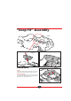


Wheels
Figure 10
Look at the 4 wheels. On one side, there are 5 mold-
ed bolts (small bumps). When installing the wheels,
this is the outside of the wheel, and should be facing
you.
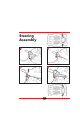
Figures 11 and 12
Slide the wheel onto the axle, and take a locking pin
A (it looks the same as the locking pin you used to
attach the steering wheel). Push in the locking pin, and
turn until it clicks into place. Then take the pin B and
insert it with a quarter twist until it snaps into place.
Figure 13
Look at the back axles. On one, is the gear box as
shown in Figure 13. Take a look at the inside of the
wheel before you slide it on. There are two notches
inside the wheel that must line up with the tabs on the
wheel axle. The easiest way to do this, is to slide the
wheel onto the axle, and twist it slowly from side to side
until it snaps into place. Then secure the wheel to the
axle with a locking pin, and the pin B.
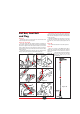
Adjustable seat
Figure 14
Your Power Rider™ seat can be adjusted for a grow-
ing child.
It fits into slots in the car body as shown in Figure 14.
For smaller children the seat fits into slots “B” and
“D”,and for taller children, into slots “A” and “C”.
To install the seat, line up the tabs with the appropri-
ate slots in the base, and snap down until it clicks into
place.
To remove the seat, look under the car and you will
see the seat tabs showing through the base. Simply
push the tabs towards the center of the car, and pull
the seat up.
Figure 10
7
Figure 13
Gear box
Tabs
A
B
C
D
Figure 14
Figure 11
A
B
Figure 12