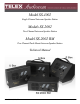
Model SS-1002 Single-Channel Intercom Speaker Station Models SS-2002 Two-Channel Intercom Speaker Station Model SS-2002 RM Two-Channel Rack Mount Intercom Speaker Station Technical Manual 9350-7741-000 Rev F 11/2010
PROPRIETARY NOTICE The product information and design disclosed herein were originated by and are the property of Bosch Security Systems, Inc. Bosch reserves all patent, proprietary design, manufacturing, reproduction, use and sales rights thereto, and to any article disclosed therein, except to the extent rights are expressly granted to others. COPYRIGHT NOTICE Copyright 2010 by Bosch Security Systems, Inc. All rights reserved.
Important Safety Instructions 1. Read these instructions. 2. Keep these instructions. 3. Heed all warnings. 4. Follow all instructions. 5. Do not use this apparatus near water. 6. Clean only with dry cloth. 7. Do not block any ventilation openings. Install in accordance with the manufacturer’s instructions. 8. Do not install near any heat sources such as radiators, heat registers, stoves, or other apparatus (including amplifiers) that produce heat. 9.
Table of Contents INTRODUCTION ....................................................................................................................................... 3 Introduction ...............................................................................................................................................................3 Description .............................................................................................................................................................
CHAPTER 1 Introduction Introduction Thank you for purchasing the Audiocom SS-1002/2002/2002RM Intercom Speaker Station. We hope the many design features of this product satisfies your intercommunication requirements for many years to come. To get the most out of you new intercom stations, take a few moments to look through this manual before using the Intercom Speaker Stations for the first time.
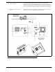
Features Use Figure 1 and Figure 2 to locate the features described below. 1. Channel and Power Connections - The U box uses quick release terminals to connect to audio and power wires. For the S box and P box versions, the terminal connections are connected to the dual, loop-through XLR connectors on the side of the box. These permit several stations to be connected in a string, or daisy-chain, using prefabricated intercom cables. 2.
13. Sidetone Trimmers - The sidetone trimmers adjust the level of the user’s own voice in the headphones when using full-cushion headphones. When using the speaker or open-ear style headphones, the sidetone trimmers are adjusted to eliminate the user’s voice from the headphones or speaker. This helps to prevent feedback. 14. Balanced/Unbalanced Selector Switch - This switch sets the intercom station for compatibility with either Audiocom (balanced) or Clear-Com (unbalanced) intercom systems. FIGURE 1.
FIGURE 2.
CHAPTER 2 Installation Configuration Pre-check Before making connections, read the following configuration notes. Make sure all internal controls are properly set for your intended usage. To access the internal controls, do the following: 1. Remove the four (4) screws on the front panel that secure the intercom station faceplate to the mounting box. 2. Pull the faceplate out for all versions (except the RM version). To access the internal controls for the RM version, do the following: 1.
Mic Kill Receive Audiocom intercom stations, such as the US2002A, can transmit an inaudible signal to turn off the microphones in all remote intercom stations on an intercom channel. This is useful when a remote intercom station has been left unattended with the microphone on. The procedure to send a mic kill signal from a master station is a two-step process, so it is very unlikely microphones are ever turned off by accident.
Speaker Beep for Incoming Call To set the speaker beep for incoming calls, do the following: > Set DIP switch 5 to the closed position if you want to hear incoming call beep in the speaker. NOTE: DIP switch 3 must be in the open position. Balanced/Unbalanced Switch This switch is set at the factory to the Balanced (BAL) position for use with Audiocom intercom systems. Set the switch to the Unbalanced, or UNBAL position for use with a Clear-Com intercom system.
When a gooseneck microphone is inserted in the panel microphone connector, the built-in panel microphone is automatically bypassed. Use either of these microphones for talk back, then use the internal speaker for listening, or connect a pair of headphones to the headset connector for private listening. Intercom Channel Connections The method of connection depends on the type of box.
Description of Locally Powered Connection Using a Locally Powered Connection, an intercom station is connected to the intercom line just like any phantom powered intercom station, except a local power supply is also connected. The external local power supply is located near the intercom station and provides power for that station only. Since power loss on the intercom lines is no longer an issue, the operating range is now limited only to the audio transmission range, which is several miles.
All Locally Powered Intercom Stations (Dry Lines) If intercom stations are widely distributed, you can dispense with a system power supply (PS2001L, SPS-2001, etc.) and use local power for each station. When no power is delivered on the intercom channels, this is known as dry-line operation. Since a system power supply is not used, a line termination must be inserted in each intercom channel for proper operation.
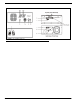
Audiocom mode connections for an SS-1002 Intercom Station in a U box. For Clear-Com connection, use the Unbalanced Mode Intercom Channel pin out information listed in “Specifications” on page 18. FIGURE 8. Audiocom mode connections for an SS-2002 Intercom Station in a U box. For Clear-Com connection, use the Unbalanced Mode Intercom Channel pin out information listed in “Specifications” on page 18. FIGURE 9.
FIGURE 10.
CHAPTER 3 Operation and Specifications Power Up To power up the SS1002/2002, do the following: 1. Verify the local power supplies are plugged in. 2. Turn on the power switches of any phantom power supplies (PS-2001L, SPS-2001, etc.). Sidetone Adjustment The SS-1002/2002 and the SS-2002RM use full-duplex audio in which the talk and listen audio are sent and received on the same wires when using a headset. The SS1002/2002 and the SS-2002RM use half-duplex audio when the speaker is used.
To adjust sidetone on SS-2002 and SS-2002RM headphones, do the following: 1. Activate channel 1. 2. Activate talk and listen. 3. Set the volume control to the normal listening level for intercom audio. 4. While talking into the microphone, use a small, flat-head screwdriver to adjust the channel 1 sidetone trimmer so you can hear your own voice in the headphones at an acceptable level. 5. Activate channel 2. 6. Repeat the steps 1 - 5 to adjust the channel 2 sidetone.
1. Turn ON the listen keys and begin your conversation. 2. Turn the keys OFF when finished. NOTE: You can turn the listen key on in either momentary or latched mode. For momentary operations, press and hold the key. For latched operation, tap the key to turn it on. Then tap it again to turn it off when finished. You can turn the talk key on in momentary mode only. Calling an Intercom Channel To call an intercom channel from the SS-2002 or SS-2002RM, do the following: 1.
Specifications Send 20kHz ±100Hz, 0.
Dimensions FIGURE 11.
20
APPENDIX A SS1002/2002 Supplemental Information Installing the Box to the Faceplate General Instructions If you ordered SS1002/2002 boxes and faceplates separately, use these instructions to assemble the speaker stations. Once you have assembled the stations, refer to the User Manual for all installation and operation information. Step 1.
TABLE 4. SS2002 Wire Connection for use in Audiocom System XLR Connector on Box Terminal Strip on Circuit Board Description Pin 1 TB1-1 Pin 2 No connection Pin 3 TB1-3 Audiocom Channel 1 audio low and +24VDC phantom power Pin 4 TB1-4 Audiocom Channel 1 audio high and +24VDC phantom power Pin 5 TB1-5 Audiocom Channel 2 audio low and +24VDC phantom power Pin 6 TB1-6 Audiocom Channel 2 audio high and +24VDC phantom power TABLE 5.
Notes 23