IMPORTANT SAFEGUARDS Read these instructions carefully and S retain them for future use. If this product Is passed to a third party, then haste Instructions must be Included. When using electrical appliances, basic safety precautions should always be followed te reduce the risk of fire, electric shock, and/or injury to persons including the following: | A WARNING | Risk of electric shock! Improper usa of this product can cause damage, shock, Injury or death.
XIII Risk of electric shock! Use spacial care when making measurements, if the voltages are greater than 25 V~ rms or 35 V These voltages are considered a shock hazard. TTS Risk of electric shock] Keep fingers away from the metal probe tips when taking measurements. I PENITENT Risk of explosion Do not use the product near explosive vapors, dust or gases. FCT Risk of Injury! The probe tips are sharp for accuracy. Be careful when handling and reattach the probe tip shrouds after use.
Mode Maximum Input 1000V fast acting fuse {max. 30 seconds every 15 minutes) 800 mA, 1000V fast acting fuse 1000 Frequency, Resistance, Capacitance, Diode 250 Test, Continuity Surge Protection: 8 kV peak per [EC 61010 Do not measure current on a CAT Ill circuitry whose voltage exceeds 1000 V. Do not measure current on a CAT IV circuitry whose voltage exceeds 600 V. When measuring volts, do not switch to current/resistance modes. Set the function switch to the appropriate position before measuring.
Verify the product's proper operation before use by measuring a known live voltage. Always discharge capacitors and remove power from the device under test before performing diode, resistance or continuity tests. Voltage checks on electrical outlets can be difficult and misleading because of the uncertainty of connection to the recessed electrical contacts. Do not use this product for checking socket outlets. Use special equipment for checking socket outlets.
Battery Warnings Always insert batteries correctly with regards to polarity {+ and -) marked on the battery and the product. Exhausted batteries should be immediately removed from product and property disposed. Keep batteries out of the reach of children. Do not dispose of batteries in fire. Remove batteries from product if it is not to be used for an extended period of time. If the battery leaks, avoid contact with skin and ayes.
This symbol, adjacent to another symbol or terminal, indicates the user must refer to the manual for further information. This symbol, adjacent to a terminal, indicates that, under normal use, hazardous voltages may be present. Product Is protected by double Insulation or reinforced Insulation. Alternating current (AC). Direct current (DC). Earth (ground) terminal/potential. Fuse Product is protected against the effects of temporary immersion in water.
Intended Use v= + This product is intended to perform electrical i gy measurements on GAT lll locations (3-phase xX — and single phase distribution) and CAT IV locations {3-phase and single phase primary over-current protection devices). * This product covers CAT Il and CAT | locations. « This product may be used only under the conditions and for the purposes for which it was designed. * No liability will be accepted for damages resulting from improper use or non-compliance with these instructions.
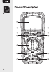
MAX/MIN button RANGE button MODE button Function switch 10A input jack uA/mA input jack REL button Hz/% button HOLD 7: button DO O00 OO VBE © YS Positive Input jack COM input jack Probe tip shrouds East probes with connector leads Rain caps Thermonuclear probe adapter with caps Thermonuclear probe Battery compartment Tilt stand Test probe holders 11
Policyholder ~~ €} A Relative Units of {I w) Continuity measurement % Percent {& Pk Diode test (duty cycle) fl Low battery & mmm Minus sign indicator (© Auto power-off {(E} AC Alternating current/voltage Display reading ~~ {} DC Direct circumferential Auto Range {> VFD Variable Indicator frequency drive mode MAX-MIN indicator
V3 14 Changing Batteries I APPETITE Risk of electric shock! Disconnect the product from any circuit, remove the connector leads (N) from the input jacks F/G) K/L). and tum OFF the product before opening the battery compartment {R}. Do not operate the product with an open battery compartment. Replace the battery when the low battery Indicator (4} Is shown on the display (A). « Open the tilt stand (S). * Loosen the screw of the battery compartment cover (R) and remove it.
* To switch the product off, set the function switch (E) to the OFF position. Automatic prows OFF * In order to conserve battery life, the product automatically emits a beeping signal that the product has been idle for 15 minutes. Right after 1 minute, the product tums off. + To tum the product on again, pass any button. «When “automatic power of” is enabled, the (% indicator (5) is Shawn on the display (A).
Changing the measurement range By default, the measurement range is set automatically and the Auto Range indicator (7) lights up. It is possible to set the measurement range manually. * Press the RANGE button (C} to activate the manual mode and to disable the automatic range setting. The Auto Range indicator (7) goes off. « By every press on the RANGE button {C) the relevant decimal place changes its position. + If reading Is higher than the measurement range, OL lights up on the display (4).
* Press the REL button (H) again to rectum to normal operation mode. The A indicator (3) goes off. This feature is not applicable for functions: Post ion Function / Measurement Resistance / diode test / continuity / o capacitance Frequency / duty cycle & Temperature Maximum/minimum measurement * Press the MAX/MIN button (B} to switch between the maximum (MAX), minimum (MIN) and maximum to minimum (MAX-MIN} range value. The appropriate MAX-MIN indicator (8) lights up.
DC voltage measurement Doing voltage measurements while the + connector lead (N} is left on the ampere input jacks (RG) will blow the product's internal fuse if it draws a current greater than the internal fuses current rating. Check that the red connector lead {N} Is on the correct terminal. Risk of damage! Do not measure motors with unstable power. Large voltage surges may occur that can damage the product. = Set the function switch (E} to the V position.
* The stabilized value on the display (A} is read as the actual reading. AG voltage measurement CTC Risk of electric shock! The contact plates of powered AC outlets may be recessed too deep for the test probes (N} to reach. This may give false measurements. Contact point of measurement must be visible for a true reading.
= Set the function switch (B} to the V~ Hz % VFD position. "AC" will be indicated on the display. Insert the black connector lead (N} into the negative COM input jack {L). * Insert the red connector lad {N} Into the positive 354% input jack (K). = Connect the test probes (N) in parallel to the circuit under test. * The stabilized value on the display (A} is read as the actual reading. VFD made {Variable-Frequency Drive) * In AC voltage measurement mode, press and hold tha MODE button (D} for 2 seconds.
Frequency Mode (V~) voltage measurement mode, press the Hz/% button Hz {Hertz) lights up. * Connect the test probes (N) in parallel to the circuit or component being measured. + The stabilized value on the display (A) is read as the actual reading.
* In AC voltage measurement mode, press the Hz/% button {) twice. % {percent} lights up. * Connect the test probes (N) in parallel to the circuit or component being measured. + The stabilized value on the display (A) Is read as the actual reading. Voltage measurements (mV) * Set the function switch {E} to the position. * Crass the MODE button {D) to switch between AC and DC mode. AG (13) or DC (14) lights up.
* Connect the test probes (N) in parallel to the circuit under test. * The stabilized value on the display (A} is read as the actual reading. Frequency mode (mV-) * In AC voltage measurement mode, press the Hz/% button Hz (Hertz) lights up. * Connect the test probes (N) in parallel to the circuit or component being measured. = The stabilized value on the display (A} is read as the actual reading. Duty Cycle mods + In AC voltage measurement mods, press the Hz/% button {) twice. % (percent) lights up.
Insert the black connector lead (N} into the negative COM Input Jack {L). « For current measurements of up to 6000 pA, set the function switch (E} to the position and insert the red plug connector lead {N) into the panama input jack (G). For current measurements of up to 600 mA, set the function switch (E} to the potion and Insert the red plug connector lead {N) Into the panama Input Jack {G).
* Tum off the power to the circuit under test. Break the connection line/track and separate securely the 2 paints where the flow of current must be measured. * Connect in series by securely attaching the test probes (N) each at the 2 open points of the track/line. = Apply power to the circuit. + The stabilized value on the display (A} is read as the actual reading. Frequency mode (AC) * In AC measurement made, press the Hz/% button Hz (Hertz) lights up.
* The stabilized value on the display (A} is read as the actual reading. Resistance measurement PF CITIZENRY Risk of electric shock! To avoid galactic shock, disconnect power from the unit under test and discharge all capacitors before taking any resistance measurements. Remove the batteries or unplug. Resistance measurements are taken with no electricity running in the circuit. For best results, disconnect one side of the component under test.
* Insert the red connector lead (N} into the positive SAP input jack (K). * 0 should light up on the display (A). + Place the test probes (N) across the cultural or part under test. * The stabilized value on the display (A} is read as the actual reading. Diode test Set the function switch (E} to the 0 +0 CAP * Insert the black connector lead {N} Into the negative COM input jack (L) * Insert the red connector lead (N} into the positive 5 SAP input jack (K).
* Press the MODE button {D) to switch to diode test mode. (11) should light up on the display (A). * Place the test probes (N) across the diode being measured. + If the diode was measured in reverse, the display {A) shows OL. Reverse the probes (N) position to get the correct polarity. Forward voltage typically indicates shorted diode indicates near 0 V and an open diode indicates OL in both polarities. Continuity check Risk of electric shack.
* Insert the black connector lead (N} into the negative COM input jack {L). Insert the red connector lead (N} into the positive Y.§ SAP input jack (K). + Press the MODE button {D) twice to switch to continuity check mode. (10) should light up on the display {A). * Place ths test probes (N) across the circuit or part under test. * The stabilized value on the display (A} is read as the actual reading. * If the resistance is less than approximately 50 0, an audible signal is emitted.
* Set the function switch (E} to the 2 -b+ 0 CAP Insert the black connector lead (N} into the negative COM input jack (1). « Insert the red connector lead (N} into the positive S85 input jack (K). + Press the MODE button {D) 3 times to switch to capacitance measurement mode. nF should light up as the unit {2}. * Place the test probes (N) across the capacitor under test. * The stabilized value on the display (A} is read as the actual reading.
When measuring electrolytic capacitors, follow the polarity -} of its leads to have a precise measurement. Frequency/duty cycle measurement (electronic) = Set the function switch (E} to the Hz % Insert the black connector lead (N} into the negative COM input jack {L). * Insert the red connector lad (N} Into the positive {4542 Input jack (K). * Place the test probes (N) across the circuit or part under test. * Press the Hz/% button {) to switch between frequency measurement (Hz) and duty cycle measurement.
* The stabilized value on the display (A} is read as the actual reading. Temperature measurement « Insert the thermonuclear probe adapter (P} with the black connector into the negative COM input jack (1) and with the red connector into the positive YEA input jack (K). * Connect the thermonuclear probe (Q} to the thermonuclear probe adapter (P). The polarity marking of the probe {Q) must correspond to the marking of the adapter (P}. The probe pins are made In varying sizes to avoid a wrong connection.
* Place the thermonuclear probe tip to the component under test. * The stabilized value on the display (A} is read as the actual reading. For longer period of measurements, use a thermal tape to attach the thermonuclear probe to the surface being measured. Risk of product damage! Disconnect the thermonuclear prob {Q) before changing to other electrical measurement mode. Cleaning and Maintenance + Switch the product off and all the & connector leads before cleaning.
Replacing the fuses PXTGIIEY Risk of electric shack! Disconnect the product from any circuit, remove the connector leads (N) from the input jacks (F/G) and tum OFF the product before opening the battery compartment (R). Do not operate the product with an open battery compartment. If the product does not work properly, check the fuses and batteries to make sure that they are still good and that they are properly inserted.
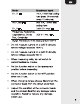
Storage = Store the product in its original packaging in a dry area. Keep away from children and pets. Specifications > As curacy specifications consist of two elements: » — (% — This is the accuracy of the measurement circuit. (+ digits) — This Is the accuracy of the analog to digital converter. Accuracy is stated and less than 75 % RH. *f.m. = from measurement DIC voltage Manga Resolution Accuracy éxmv 0.01 mv . LL OMY vamp +0.9 % f.m.* +9 digits 6V__ 0.001V . eV 001V +0.5 % f.m.
AC voltage kHz) Range Resolution Accuracy émv_ 0.01mv 600 f.m.” +9 digits 6V_ 0.001V Ca OV 001V +0.8 % f.m." +3 digits 600V 01V Lo 1000V 1v +0.8 % f.m.* 18 digits * All AC voltage ranges are specified from 5 % of range to 100 % of range. = AC voltages bandwidth: kHz (sinusoidal); 50/60 Hz {all waves). VED Sangs Resolution Accuracy 50-700V 01V/1V +4 % f.m.* £3 digits DC current Range Resolution Accuracy 600 pA 0.1 pA 6000 pA 1uA Tearoom 00TmA +1 % f.m.* +3 digits 600 mA 0.
DC current Range Resolution Accuracy 6.000A 0.001A 1A 001A +1.5 % f.m.” +3 digits 10 A: Max. 30 seconds with reduced accuracy. AC current Range Resolution Accuracy 600 pA 0.1 pA 6000 pA 1pA 60mA 0.01 mA 600 mA 0.1 mA Loa oA oo a +2.0 % f.m.* +3 digits * 10 A: Max. 30 seconds with reduced accuracy. * All AC current ranges are specified from & % of range to 100 % of range. * AC current bandwidth: kHz (sinusoidal); 50/60 Hz {all waves). +1.6 % f.m.
Resistance Range Resolution Accuracy 6000 0.10 +1.0 % f.m.* +2 digits 6kQ 0.001 kQ 60 kQ 0.01 kQ 0.8 % f.m.” +2 digits 600 0.001 MO +1.2 % f.m.* +2 digits 60MQ C.01MQ +1.0 % f.m.” +5 digits Test current: <0.35 mA, Capacitance Range Resolution Accuracy 99.99nF* 0.01nF 5.0 % f.m.* +20 digits 999.9 nF 0.1 nF 9.999 uF 0.001 UF 99.99uF 0.01 F 993.9uF OA F 98.999 mF 0.001 mF 99.99 mF 0.01 mF nF not specified 4.0 % f.m.” +5 digits +10 % f.m.
Frequency (electronic) Range Resolution Accuracy 9.999 Hz 0.001 Hz 99.99Hz 0.01 Hz 999.9 Hz 0.1 Hz 9.899 kHz 0.001 kHz +0.1 % f.m.* +4 digits 99.98 kHz 0.01 kHz 999.8kHz 0.1 kHz 9.899 MHz 0.001 MHz Sensitivity: 0.8 V ms minimum duty cycle and <100 kHz; 5V rms minimum duty cycle and >100 kHz. Frequency (electrical) Manga Ultrasonic Accuracy 10Hzto10kHz 0.01 Hz +0.5 % f.m.
Duty cycle Range Habitation Accuracy 0.1t099.98% 01% +1.2% fm> +2 digits Pulse width: 100 ys to 100 ms Frequency: 5 Hz to 150 kHz. Continuity Measurement Output Test current Reaping tone when max. 0.35 mA resistance is less then (500) Diode Measurement Output Test A=== is max. Forward voltage drop 0.9 mA, open circuit of diode voltage max. 3.2 V Temperature Range Habitation Accuracy -40 *Cto 1°C +3 % f.m.* £3 °C +1000 #3%Imrs5eF 1832 °F **Probe accuracy not included.
Power supply: Max. measurement voltage: Pollution degree: I mailing: Shock proof drop test): Croat factor: Display: Measurement rate: pit mischance: AC response; ACV bandwidth: General 1x9V battery CAT lil: 1000 V Cat IV: 600 V 2 P87 6.5' (2m) <3 at full scale up to 500 V, decreasing linearity to <1.5 at 1000 V. Fuse 1: 0.8 A1000V ceramic fast blow Fuse 2: 10 A/1000 V ceramic fast blow.
Operating temperature: 41 °F to 104 Storage temporal. 4 toff 140°F Operating humidity: max. decreasing linearly 104 °F {+40 °C). Storage humidity: <80 % Operating altitude. max. 7000" (2000 m} Aue power off After approx. 16 minutes Dimensions: 3.2x22x7in 179 mm} Net weight: 1 Ibs {450 g) Battery Disposal Rm not dispose of sad batteries with Ror household waste. Take them to an appropriate disposal/collection site.
Feedback and Help Love it? Hate it7 Let us know with a customer review. Amazon Commercial is committed to delivering customer-driven products that live up to your high standards. We encourage you to write a review sharing your experiences with the product.