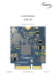
LockitModule ACN-LM Integrators Manual LockitModule Version 0.9 (18.10.
Table of Contents 1 Introduction ...................................................................................................................................................................... 3 2 Specifications .................................................................................................................................................................... 3 3 4 5 2.1 Physical Dimensions ........................................................................................
1 Introduction The LockitModule ACN-LM offers to implement timecode and sync capabilities plus metadata processing based on a modular NVMe form factor plug in card. It features industry standards such as SMPTE 12M, MIDI timecode, ITU/REC tri-level video sync, audio wordclock and multiple pulse per frame camera shutter sync. The module also seamlessly integrates Ambients ACN, an IEEE802.15.4 based, wireless sync and metadata network.
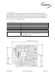
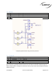
2.2 Block Diagram Local Oscillators SPI Flash MCU VCTCXO 19.2 MHz MEMS 32.768 kHz MEMS 16 MHz Timecode and Sync LTC, TLS, Wordclock, PPF, PPS 32 MB, 256 Mbit ACN RF Unit Control IEEE 802.15.4 2.405 - 2.480 GHz UART, USB, GPIO ACN RF Connector Board Edge Connector U.FL (Ipex) M.2 NGFF, type “E” Key 2.2.1 Local Oscillators The circuitry is driven by 3 frequencies, , the reference oscillator, a tunable VCTCXO @ 19.2 MHz with .
2.2.8 ACN RF Connector “ANT” carries the ACN IEEE802.15.4 RF signal via a standard U.FL socket. If RF output is not disabled permanently with no option of alteration through the user this connection must be properly terminated with a compliant 50 Ohms IPEX lead and suited antenna with max 2dBi in the according range. LockitModule Version 0.9 (18.10.
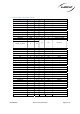
3 Board Edge Connector Pinout Signal Type Pin Pin VCC VCC SWCLK SWDIO TRACESWO N_Reset N_StandBy USB Data+ USB DataUSB VBUS UART1_RX (ACN) PWR PWR * Int. * Int. * Int. * Int. * Int.
3.1 Power The module requires only one single power supply voltage with 3.3 V. An optional extra input (VBAT) can be used to supply the internal RTC of the microcontroller Pin 1, 3 2, 4, 74 64 74 Name VCC GND 1V8 VBAT Type Description Power input, 3.3V DC stabilized, rated 250mA min. Ground Signal and power ground PWR Regulated DC output. Max. load 50 mA PWR Power input for internal RTC 2.2 -5.5V DC, max. 5µA. PWR Exemplary implementation of a RTC backup battery 3.
Exemplary implementation of pull-up resistor 3.4 Communication Interfaces 2 physical host interfaces, UART and USB HID, are available to control and inquire status of the module. The API documentation is available as separate document. UART Pin Name Type Description 21 UART_RX D 3.3V TTL, 5V tolerant 23 UART_TX D 3.3V TTL The serial 3V TTL UART1 interface is the most preferable interface for low level connection. A level shifter will be required for communicating over RS232.
3.5 LEDs Pin 6 8 44 Name LED Red LED Green LED Blue Type O O O Description Status indicator, 3.3V, active low Status indicator, 3.3V, active low Status indicator, 3.3V, active low RGB LED outputs allow to visualize the status of generator and ACN activity. It is strongly recommended to connect LEDs for debugging and optimum user experience. Exemplary implementation of an RGB LED for status display LockitModule Version 0.9 (18.10.
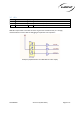
3.6 Buttons Pin 38 40 42 Name Button Green Button Red Button Pwr Type I I I Description Momentary input Momentary input Momentary input Exemplary implementation using momentary switches 3.7 Timecode Pin Name Type Description 10 LTC In I 1.8 – 5V 14 Wordclock O 3.3V TTL 16 LTC Out O Buffered output, variable from mic level to 3.3V TTL max. 39 LTC Out 2 O 1.8V TTL Timecode is available on 2 pins of the module. Pin 39 supplies 1.8V logic signal for internal use.
LTC_OUT2 on pin 39 is a direct connection to the processor and optimized for direct internal connection. When made available for external access we recommend a current limiting in line resistor, DC decoupling and tie to GND for defined DC state. Exemplary circuit for external use of LTC_OUT2 3.8 Sync Pin 14 35 Name Wordclock PPF Type O O Description Wordclock audio, 48/96/192KHz selectable, 3.3V TTL Pulse-Per-Frame output, 1-4 x Proj. FPS selectable, 3.
46 GPIO5 48 GPIO6 50 GPIO7 52 GPIO8 54 GPIO9 56 GPIO10 58 GPIO11 60 GPIO12 62 GPIO13 Reserved for internal use I/O I/O I/O I/O I/O I/O I/O I/O I/O 3.12 Analog inputs 4 general purpose analog inputs, with firmware dependent functionality: Pin Name Type 66 AI1 Analog 68 AI2 Analog 70 AI3 Analog 72 AI4 Analog reserved for internal use Description Analog input 1. Input range: 0 to 1.8 V Analog input 2. Input range: 0 to 1.8 V Analog input 3. Input range: 0 to 1.8 V Analog input 4. Input range: 0 to 1.
3.14 SPI lines Pin Name 43 SPI CLK 45 SPI MOSI 47 SPI MISO 49 SPI NSS1 Reserved for internal use Type O O I O Description SPI clock ,1.8 V logic SPI master output ,1.8 V logic SPI master input ,1.8 V logic, 5V tolerant SPI slave select ,1.8 V logic 3.15 I²C Interface Pin Name Type 51 I²C 1 SCL 53 I²C 1 SDA 55 I²C 2 SCL 57 I²C 2 SDA Reserved for internal use/OLED display. 4 Description 1.8V TTL 1.8V TTL 1.8V TTL 1.8V TTL Regulatory Requirements 4.
(1) This device may not cause harmful interference, and (2) this device must accept any interference received, including interference that may cause undesired operation FCC §15.105 (b): Note: This equipment has been tested and found to comply with the limits for a Class B digital device, pursuant to part 15 of the FCC Rules. These limits are designed to provide reason-able protection against harmful interference in a residential installation.
(2) This device must accept any interference, including interference that may cause undesired operation of the device. Le présent appareil est conforme aux CNR d’Industrie Canada applicables aux appareils radio exempts de licence. L’exploitation est autorisée aux deux conditions suivantes: 1) l’appareil ne doit pas produire de brouillage; 2) l’utilisateur de l’appareil doit accepter tout brouillage radioélectrique subi, même si le brouillage est susceptible d’en compromettre le fonctionnement.
This device complies with the RF exposure SAR test exclusion requirements for portable devices, if a minimum separation distance of 15mm is kept. However, the device shall be used in such a manner that the potential for human contact during normal operation is minimized LockitModule Version 0.9 (18.10.
5 Contact Information, Support Ambient Recording GmbH Schleissheimer Str. 181c 80797 Munich, Germany Phone: +49 (0) 89 360 55 100 E-Mail: info@ambient.de Web: ambient.de Further documentation, firmware updates, and more: ambient.de/downloads/ LockitModule Version 0.9 (18.10.