
User Manual


LockitModule Version 0.9 (18.10.2021) Page 10 of 17
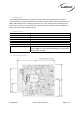
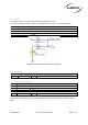
3.6 Buttons
Pin
Name
Type
Description
38
Button
Green
I
Momentary input
40
Button
Red
I
Momentary input
42
Button
Pwr
I
Momentary input
Exemplary implementation using momentary switches
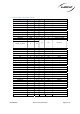
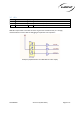
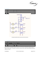
3.7 Timecode
Pin
Name
Type
Description
10
LTC In
I
1.8
–
5V
14
Wordclock
O
3.3V TTL
16
LTC Out
O
Buffered output, variable from mic level t
o 3.3V TTL max.
39
LTC Out 2
O
1.8V TTL
Timecode is available on 2 pins of the module. Pin 39 supplies 1.8V logic signal for internal use. Pin 16
gives the option to gradually reduce the level from 3V TTL down to mic level to adapt the signal to
different requirements. This signal can directly be used to jam sync with external equipment without
additional circuitry.