
User Manual


LockitModule Version 0.9 (18.10.2021) Page 4 of 17
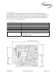
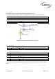
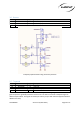
2.2 Block Diagram
2.2.1 Local Oscillators
The circuitry is driven by 3 frequencies, , the reference oscillator, a tunable VCTCXO @ 19.2 MHz with
.1 ppm frequency stability in the temperature range from -30 °C to +70 °C and auxiliary frequencies
@ 32.768 KHz and 16 MHz.
2.2.2 MCU
STM32L4R5xx microcontroller.
2.2.3 SPI Flash
For various tasks like firmware update, parameter storing and event logging.
2.2.4 Timecode and Sync
Main signal in-and outputs to sync with external equipment
2.2.5 Control
Access to the units parameters, configuration and status indication.
2.2.6 ACN RF
The ACN sync and metadata network builds on the IEEE802.15.4 LR-WPAN standard in the 2.4GHz,
approved for on globally license free use. Channels are fixed and can be selected using the API. If
desired, the RF part can also be completely disabled.
ACN Channel
Off 11 12 13 14 15 16 17 18 19 20 21 22 23 24 25 26
Freq. (MHz) RF Muted
2405
2410
2415
2420
2425
2430
2435
2440
2445
2450
2455
2460
2465
2470
2475
2480
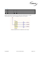
2.2.7 Board Edge Connector
All signal and control lines to operate the LockitModule are through a single type “E” NGFF M.2
connection. Note that the pinout is proprietary and not compatible with other interfaces using the
same keying.
MCU
Board Edge Connector
M.2 NGFF, type “E” Key
Timecode and Sync
LTC, TLS, Wordclock, PPF,
PPS
Local Osci
l
lators
VCTCXO 19.2 MHz
MEMS 32.768 kHz
MEMS
16 MHz
ACN RF
Unit
IEEE 802.15.4
2.405 - 2.480 GHz
SPI Flash
32 MB, 256 Mbit
Control
UART, USB, GPIO
ACN RF Connector
U.FL (Ipex)