
User Manual


LockitModule Version 0.9 (18.10.2021) Page 7 of 17
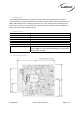
3.1 Power
The module requires only one single power supply voltage with 3.3 V.
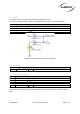
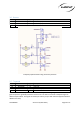
An optional extra input (VBAT) can be used to supply the internal RTC of the microcontroller
Pin
Name
Type
Description
1, 3
VCC
PWR
Power input
, 3.3V DC
stabilized, rated 25
0mA min
.
2, 4, 74
GND
Ground
Signal and power g
round
64
1V8
PWR
Regulated DC
output
.
M
ax.
load
50 mA
74
VBAT
PWR
Power input for
internal
RTC
2.2
-
5.5V DC,
max. 5
µA.
Exemplary implementation of a RTC backup battery
3.2 Aux DC Out
Pin
Name
Type
Description
64
1V8
Power
O
utput
for external Pull
-
Up resistor
s
. Max. load 50 mA
3.3 System debug signals
Pin
Name
Type
Description
5
SWCLK
* Int.
Serial Wire Clock
7
SWDIO
* Int.
Serial Wire Data In
-
/Output
9
TRACESWO
* Int.
Serial Wire Trace Output
11
NRST
* Int.
Reset,
low active, connect to pin 64 via ext.
10K resistor
13
NSTB
* Int.
Standby,
low active
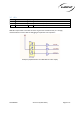
NRST may be used for a hard reset of the microcontroller by momentary pulling to ground. If not
connected to other logic tie to 1.8V (available on pin 64) with a 10K resistor to prevent accidental
reset.