
User Manual

Model: GW3030v2
Revision P1A
USER MANUAL
Gateway GW3030 v2.0
Ambient Systems B.V.
Page 8 of 15
Demmersweg 66 • 7559 BN Hengelo • The Netherlands
T: +31 88 2624368 • F: +31 88 2624399 • www.ambient-systems.net
KvK: 08122911 • VAT NL: 81297625381
CHECK.TRACK.TRACE.
4.3 Installation
Once the Gateway has been turned ON, it is ready to be installed and mounted. Please have a look at the User
Manual of the 3000 Series on how to go about installing 3000 Series networks e.g. to determine where to
install a Gateway and how to orient antennas.
For correct operation of the device, none of the communication cables (USB and RS232) must have a length
larger than 3 meters.
4.4 Mounting
The Gateway is best mounted using the GW/MR/ESP Mounting Bracket (order number 900.200.060.001).
Please, follow the instructions that come with the bracket.
4.5 Verifying Operational Status
Once Gateway has been mounted, its operational status can once more be verified by using Ambient Studio.
Use the Ambient Studio ‘Map’ view to visualize the links in the system and in particular that of the device in
question. The operational status can also be verified using the LED indication on the device.
4.6 Periodic monitoring
5 LED Behavior
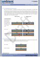
5.1 Position of the LEDs
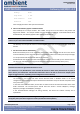
The Gateway is equipped with two LEDs, one provides an indication of the power source and one provides
feedback on the network status. Please note that in the picture below the antenna is oriented to the upper
side.
A solid color in the LED figures indicates that the LED burns constantly in the particular color. A dotted color
means that the LED blinks in the indicated color.
5.2 Boot
When the Gateway is powered on, the device will initiate a short boot sequence of a few seconds. During this
period the RED network status LED will burn for a short period.
Power LED
Network LED