
User's Manual

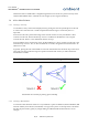
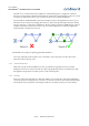
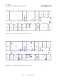
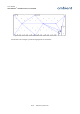
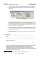
Table Of Contents
- 1 Preface
- 2 Introduction
- 3 Product Overview
- 4 Ambient Network
- 5 Installation
- 6 Configuration
- 7 Deployment
- 8 Example Deployments
- 9 Firmware Upgrades
- 10 Troubleshooting
- 11 Appendices

User Manual
3000 SERIES 3
rd
GENERATION ACTIVE RFID
SmartPoint and its available links to neighbouring Infrastructure nodes. It is placed correctly when
all the indicated RSSI values of all links are -80 or higher (i.e less negative numbers).
7.4 A Few More Pointers
7.4.1 Placing a Gateway
As said before, always start network deployment by placing the GW. The optimal place for the GW
is in the center of the network. A small example in Illustration 30 gives an idea why this is so
important.
In network A the GW is placed at the edge of the network. In this case only one MR has a direct
connection to the GW. The maximum hop count is 2. Furthermore all MRs have only one path
towards the GW. There is a clear bottleneck situation at hop 1.
In network B the GW is placed in the centre. All three MRs have a direct connection to the GW so the
maximum hop count is 1. Also, no direct bottlenecks are visible, though the SP load still needs to be
taken into account.
In general, placing the GW in the middle of a network will minimize the maximum hop-count and it
will result in (at least in the first hop) more paths towards the GW. Latency is reduced and more
bandwidth is available.
Place the Gateway as much in the centre of the network as possible!
7.4.2 Placing a MicroRouter
You will encounter situations where it is very beneficial to place an additional, albeit redundant, MR.
Network stability and coherence, bandwidth, coverage, latency, these are all aspects that can benefit
the network performance greatly by simply adding an additional MR. See Illustration 31 for an
example.
52/73 Ambient Systems B.V.
Illustration 30: Pointer for placing your Gateway