
Quick Start Guide
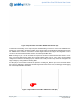


Table Of Contents

Apollo3 Blue Plus EVB Quick Start Guide
QS_A3P_1p00 Page 11 2019 Ambiq Micro, Inc.
All rights reserved.
6. Power Supply Options and Measuring Current
There are three power supply options for the Apollo3 Blue PlusEVB:
▪ Operate at 3.3V as provided by the on-board power supply
▪ Operate at 1.8V as provided by the on-board power supply
▪ Provide externally supplied power
Figure 6 shows header P19 which is used to select a power configuration through jumper installations, as
well as the option to measure the supply current to the MCU with an ammeter. Solder bridge SB15 can be
filled instead of jumpering from pin 1 to pin 2 if current measuring is of no interest.
Figure 6. Voltage Selection on Header P19
Table 2 shows valid jumper configurations for P19. All other configurations are invalid. Note that a jumper
across pins 7 and 8 is not necessary and does not do anything - the pins are available only for easy access
to ground.
Table 2: Jumper Configuration for Power Selections
Jumper
1-2
Jumper
3-4
Jumper
5-6
Power Source
In In Out 3.3V operation from internal regulator
In In In 1.8V operation from internal regulator
Out In Out
Intended for current measuring across pins 1 and 2
during 3.3V operation from internal regulator
Out In In
Intended for current measuring across pins 1 and 2
during 1.8V operation from internal regulator
In Out Out
Externally-provided supply voltage within the allowable
range (1.755-3.60V) on pin 3 or 5
Out Out Out
Intended for current measuring across pins 1 and 2
during externally-provided supply voltage within the
allowable range (1.755-3.60V) on pin 3 or 5
_1.8V