
Quick Start Guide
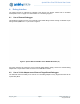
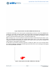
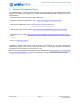
Table Of Contents

Apollo3 Blue Plus EVB Quick Start Guide
QS_A3P_1p00 Page 9 2019 Ambiq Micro, Inc.
All rights reserved.
Figure 4. Apollo3 Blue Plus EVB’s DEBUG OUT Header (J2)
To utilize this functionality, use a 10-pin low-pitch standard debug connector to connect the “DEBUG OUT”
header (J2) on the EVB to the debug header on the target board. The EVB will automatically detect when
the “DEBUG OUT” header is connected to another target board and reconfigure the integrated J-Link to
connect to this external board rather than the on-board Apollo3 Blue Plus.
Note: A voltage on pin 1 of the J2 header is required for the above mentioned automatic switch to occur.
Also, if the target VDD doesn't match the on-board voltage (either 3.3V or 1.8V), and to avoid possible
voltage level conflicts on the debug I/O port, VDDIO of the J-Link processor may need to be changed to the
target voltage by cutting SB5 and shorting SB6.
An LED (D3) is on the board to indicate the presence of VDD_EXT_DBG on pin1 of the J2 header. When
D3 is ON, the debugger is debugging external target board. When D3 is OFF, the debugger is debugging
the on-board Apollo3 Blue Plus MCU.
Figure 5. Apollo3 Blue Plus EVB’s DEBUG OUT LED (D3)