
User manual


14 K0461 issue 1 - [EN] English
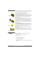
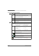
5.2 Indicator
assembly
Optional item (MC 620-IS/PM620-IS). See figure B2 (front cover).
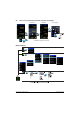
5.3 Electrical
connections
See figure C1 to C4, and D1 (front cover).
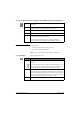
5.4 External pressure
connections
See figure B1/E1 (front cover). Use an applicable method to seal
the external pressure connections, and then tighten to the
applicable torque.
5.5 Maintenance Clean the case with a moist, lint-free cloth and a weak detergent.
Do not use solvents or abrasive materials.
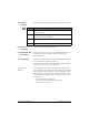
Return the instrument to the manufacturer or an approved service
agent for all repairs. Refer to the user manual.
European Union
directives
Do not dispose of this product or its battery as household waste.
Use an approved organisation that collects and/or recycles waste
electrical and electronic equipment, and/or used batteries. This
will help keep to a minimum the effect these items have on the
environment and on human health. For more information, contact
one of these:
• our customer service department:
(Contact us at www.gesensinginspection.com)
• the local government office.
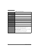
B2 Step Procedure
1. Align the two slots (a) on the calibrator with the two posts (b) on
the module carrier.
2. When the posts are fully engaged in the slots, tighten the two
screws until they are hand-tight.
3. Attach one or two PM620-IS modules with the correct range and
type.
4. Tighten each one until it is hand-tight only.
Maintenance/Specification