IMPORTANT SAFETY INSTRUCTIONS When using this electronic device, basic precautions should always be taken, including the following: 1. Read all instructions before using the product. 2. Do not use this product near water (e.g., near a bathtub, washbowl, kitchen sink, in a wet basement or near a swimming pool etc). 3. Use this device when you are sure that amplifier has a stable base and it is fixed securely. 4.
CONTENTS: Before you start Introductions Features 4 4 Operation Front and rear view Front panel Rear panel Function description 5 6 6 7 Controls and connectors Connectors 8 Specifications General specifications 11
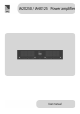
Introduction iA a group of amplifiers for professional contractor market. 100 V amplifiers with different channel number and output power configuration. Fan powered cooling system, rack mount. Amplifiers are designed to work under hard conditions and required minimum maintenance after installation. Used in a medium and large public address or voice evacuation systems.
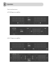
Front and rear view iA2X250 power amplifier iA4X125 power amplifier
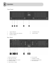
Front Panel 1. 2. 3. Signal indicator Output configuration indicator Protect indicator 4. 5. Ventilation holes Power switch Rear Panel 1. 2. 3. 4. 5. Balanced XLR input Input gain control Output configuration switch Ventilation holes Input mode selector 6. 7. 8. 9.
Functions description SIGNAL INDICATOR Signal LED indicates audio signal in the amplifiers input. OUTPUT CONFIGURATION INDICATOR Amplifier output can be configured for 4Ω, 70V and 100V audio system by using switch in the rear panel. Output configuration LED indicates what kind of sound system is selected. Configuration depends on the connected speaker type.
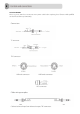
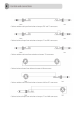
AC FUSE HOLDER Please use 6.3A, 250V fuse. Disconnect main power cable before replacing fuse! Contact with qualified service if fuse blows up constantly. Connectors TS connector TRS connector XLR male connector XLR female connector RCA connector Cable wiring examples Cable to balanced input from balanced output. TRS connectors.
Cable to unbalanced input from balanced output. TRS and TS connectors. Cable to balanced input from unbalanced output. TS and TRS connectors. Cable to unbalanced input from unbalanced output. TS connectors. Cable to balanced input from balanced output. XLR connectors. Cable to unbalanced input from balanced output. XLR and TS connectors. Cable to balanced input from unbalanced output. TS and XLR connectors.
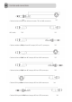
Cable to balanced input from balanced output. TRS and XLR connectors. RCA cable. Cable to unbalanced input from RCA output. RCA and TS connectors. Cable to balanced input from RCA output. RCA and XLR connectors. Cable to balanced input from RCA output. RCA and TRS connectors. Cable to RCA input from balanced output. RCA and XLR connectors. Cable to RCA input from balanced output. RCA and TRS connectors.
General specifications iA2X250 Power supply Output power Total harmonic distortions Input sensitivity Max input level Gain control S/N ratio Frequency response Cooling Indicators Output Weight Dimensions iA4 X125 AC 220 V / 50 Hz 2 x 250 W 4 x 125 W < 0,1 % 0 dBu +20 dBu Min position -∞ Max position 0 dB 95 dB 20 Hz – 20 kHz Fan powered cooling system Signal, protection, output configuration 100 V, 70 V, 4 Ω 7,4 kg 9,7 kg 432 mm (W) x 88 mm (H) x 425 mm (D) The specifications above are correct at the tim
AMC is a registered trademark of AMC Baltic www.amcpro.