POWER MASTER **Premium MPPT Series** SOLAR CHARGE CONTROLLER PM-SCC-50AM / PM-SCC-80AM PM-SCC-40AMW / PM-SCC-80AMW Installation and Operation Manual
Chapter 1 Installation 1.1 Loads Requirement The Premium MPPT Series plays a major role in planning your PV system. The first step in planning an efficient PV system is to calculate the load requirement. In order to calculate the anticipated load requirement, it is important to determine average and peak load consumption. The possible load growth should also be taken into consideration when planning the load requirement because loads hardly remain static and they grow more frequently than they reduce. 1.
1.5 Shunt (BCS) The Shunt is an optional component and it is required for the Premium MPPT Series to achieve to the optimal operation levels and it functions as a hub for connecting measurement sensors. The main purpose of the shunt is to allow the Premium MPPT Series to measure current drawing into and out of the battery. DC load centers is where the Premium MPPT Series Shunt is recommend to be placed at. Or installing it in an electrical enclosure is also acceptable.
1-3
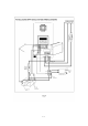
1.9 Installation Steps Example: PM-SCC-80AM Before starting the PM-SCC-80AM, keep the breakers, controllers in OFF position. 1. Locate the battery and Premium MPPT Series and make sure the safety distance is at least 1 meter long. 2. Install a 100 Amp rated DC breaker and connect it to the Battery + . 3. Install a Shunt of rated 500A/50mV and connect it to the Battery –. 4. Connect the BAT+ terminal of the Premium MPPT Series to the DC breaker. 5.
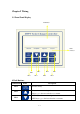
Chapter 2 Wiring 2.1 Front Panel Display LCD Meter LED Indicator PB 3 PB 4 PB 8 PB 7 PB 2 PB 6 PB 1 PB 5 8 Push Buttons Push buttons Name Description PB1 Data write-in key PB2 UP key to increment setting values. UP key to go to the next selection or constant. PB3 DOWN key to decrement setting values. DOWN key to go to the last selection or constant.
PB4 Reset key to reset the fault. ESC key to return to the last selection level. PB5 Quick function key to the Main Menu: Data Log PB6 Quick function key to the Main Menu: Programming PB7 Quick function key to the Main Menu: Initialize PB8 Quick function key to the Main Menu: Operation 4 LED Indicators LEDs Flashing/ Solid Description Read the LCD meter for fault condition displayed.
2.
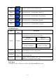
J MA1 Connecting terminal for the contact A of auxiliary 1 K MC1 Connecting terminal for the common contact of auxiliary 1 L MB1 Connecting terminal for the contact B of auxiliary 1 M MA2 Connecting terminal for the contact A of auxiliary 2 N MC2 Connecting terminal for the common contact of auxiliary 2 O MB2 Connecting terminal for the contact B of auxiliary 2 P PV+ Connecting terminal for Solar Array Positive Q GND Connecting terminal for Solar Array Negative R BAT+ Connecting terminal fo
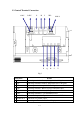
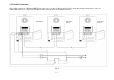
2.3 Parallel Connection The parallel connection of Premium MPPT Series can be up to 16 units (1 Master and 15 Slaves) and in the parallel system, there is only one Shunt which needs to be connected to the Master unit to measure the total accumulated current.
Chapter 3 User Constants 3.1 The following is the structure of user constants. Constants Tree GROUP MENU Operation U-01 U-02 U-03 U-04 U-05 U-07 U-08 U-09 U-10 U-11 U-12 U-13 U-14 U-15 U-16 U-17 IN =xxx.xV xxx.xAmps OUT =xxx.xV xxx.
3. 2 The following is the “Initialization Stage Flow Chart”.
SAVE: If SAVE is selected by pressing key, the controller will save the entered settings and operate with them RCLL (RECALL): Pressing key will return to the last setting prior to entering setup. DFLT (DEFAULT): If DFLT is selected by pressing key, the controller will revert to and operate at default settings based on the original voltage, battery type and capacity entered in the initialization process.
3.3 The following is the “Operation Stage Flow Chart”.
Main Menu-Initialize Menu Constants Main Menu-Programming Group B Menu Group Constants Edit Constants 3-5 Constants Edit Data Enter Data Enter
Main Menu-Programming Group C Menu Group Constants Constants Edit Data Enter Main Menu-Programming Group D, D-01= ON or OFF Menu Group Constants 3-6 Constants Edit Data Enter
Main Menu-Programming Group D, Auxiliary 1 ON/OFF Condition Setting Menu Group Constants Constants Edit Data Enter *** Main Menu *** Operation ▲ *** Main Menu *** Initialize ▲ DATA ENTER Group B Battery Setup *** Main Menu *** Programming ESC RESET ▼ ▲ Group C MPPT Setup ▼ ▲ DATA ENTER Group D Auxiliary Relay 1 ▼ ▲ ▼ ▼ ▲ ▼ ▲ Entry Accepted DATA ENTER Set Aux Relay 1 Mode D-01= Solar Voltage Entry Accepted DATA ENTER ▲ Aux RY1 ON Condition Aux RY1 ON Condition D-02= <000.
Main Menu-Programming Group E, Auxiliary 2 ON/OFF Condition Setting Menu Group Constants 3-8 Constants Edit Data Enter
Main Menu-Programming Group F Menu Group Constants 3-9 Constants Edit Data Enter
Main Menu-Programming Group O Menu Group Constants 3-10 Constants Edit Data Enter
Main Menu-Data Log Menu Constants Constants Edit 3-11 Data Enter
Chapter 4 Constant List Main Menu Group Constant U-00 Operation U LCD Display IN =xxx.xV xxx.xAmps OUT =xxx.xV xxx.xAmps Range ─ Unit 0.1V Factory Setting Remark Page ─ 5-1 0.1A U-01 Input Voltage ─ 0.1V ─ 5-1 U-02 Input Current ─ 0.1A ─ 5-1 U-03 Output Voltage ─ 0.1V ─ 5-1 U-04 Output Current ─ 0.
Main Menu Group Constant B-05 LCD Display Unit 0~80 1A ─ 13.9~15.2 0.1V 14.6 5-6 AGM 13.7~15.1 0.1V 14.1 5-6 GEL 13.6~15.1 0.1V 14.1 5-6 1 Min 2 Hr 5-7 12.9~14.2 0.1V 13.8 5-7 BAT. MAX Charge Amps FLOOD- B-06 B-07 ED Set Absorption Volts 0~ 99 Hr Set Absorption Time 59 Min FLOOD- B B-08 Setting Remark Page NOTE 6 5-6 Set Float ED Voltage AGM 12.8~14.2 0.1V 13.2 5-7 GEL 12.8~14.1 0.1V 13.5 5-7 12V:15.6 12V:14.7~16.
Main Menu Group Constant LCD Display Range Unit Factory Setting Remark Page Auxiliary Relay 1 OFF, ON, Solar Voltage, Output Volts, Battery Volts, OUT Current, D-01 Set Aux Relay 1 Mode BATT Current, ─ OFF See See Below Below 5-9 Temp. Battery Temp. Time Battery SOC, Output Volts Aux RY1 ON Condition Programming D D-02 5-10 When D-01= Solar Voltage 0~150/0~250 0.1V 0 5-10 When D-01=Output Volts 0~64 0.1V 0 5-10 When D-01=Battery Volts 0~64 0.
Main Menu Group Constant LCD Display When D-01= D-03 D 00~23 Hr Premium MPPT Time When D-01=Battery SOC D-04 Range Aux RY1 MIN. ON time 00~59 Min 0~100 0~23 Hr, 0~59Min Unit Factory Setting Remark Page 1 Min 0 5-11 1% 0 5-11 1 Min 0 5-11 ─ OFF 5-12 See See Below Below Auxiliary Relay 2 OFF, ON, Solar Voltage, Output Volts, Battery Volts, OUT Current, E-01 Set Aux Relay 2 Mode BATT Current, Temp. Battery Temp.
Main Menu Group Constant E-03 E LCD Display Unit When E-01=OUT Current 0~80 1A 0 5-12 When E-01=BATT Current -500~500 1A 0 5-12 When E-01=Premium MPPT Temp -20~100 1℃ 0 5-12 When E-01=Battery Temp. -20~100 1℃ 0 5-12 When E-01= 00~23 Hr 1 Min 0 5-12 1% 0 5-12 1 Min 0 5-12 Premium MPPT Time When E-01=Battery SOC E-04 Factory Range Aux RY2 MIN.
Data Log G G-09 Clear Energy Harvest Today’s Data Logged Data ─ Today’s Data NOTE 1 (U-12, U-13, U-14, U-15) Battery SOC, Battery Current and Battery Amp Hours will only be visible when terminal BVS (Battery Voltage Sensing) is connected to the battery and will only be active when using an optional 50mv/500amp external shunt.
NOTE 3 (B-09, B-10, B-11, B-12) These constants are only displayed if Flooded is selected as battery type (B-02). NOTE 4 (C-02, C-03, C-04, C-05) C-02 is only displayed if P and O or Scan and Hold is selected as MPPT Type (C-01). C-03 and C-04 are only displayed if Percentage is selected as MPPT Type (C-01). C-05 is only displayed if Hold Input V is selected as MPPT Type (C-01). NOTE 5 (U-16, F-02) U-16 and F-02 are only displayed if Slave is selected as Premium MPPT Network MODE (F-01).
Chapter 5 Programming Constants *** Main Menu*** Operation U-00: IN=xxx.xV xxx.xAmps OUT=xxx.xV xxx.xAmps z Use Constant U-00 to monitor the power coming in from the PV array in Volts and Amps. The second line displays the power going out of the Premium MPPT Series, it also displays in Volts and Amps. z In most installations there will be a difference between incoming volts and outgoing volts. This reflects the flexibility of the Premium MPPT Series with respect to PV array input voltage vs.
U-07: EnergyHarvest Today 2 z This screen displays how much time the charger was in Float mode “Today” in Hour:Minute. U-08: Stage of Charger z This screen displays the charging stage of Premium MPPT Series. The possible values are Charger Off, Charger Start, BULK Stage, ABSORP Stage, FLOAT Stage, Charger MPPT, Charger Stop, EQUALZ Stage. U-09: Premium MPPT Series Date z This screen displays the date according to the setting of initialization stage. The display format is MM/DD/YY.
and will only be active when using an optional 50mv/500amp external shunt. ※ U-13 will only be displayed when the terminal BVS (Battery Voltage Sensing) is wired to the battery. To show the precise values, an optional 50mv/500amp external shunt is needed. U-14: Battery Amp Hours z This screen displays the battery capacity in AHr (Amp Hours).
*** Main Menu*** Initialize A-01: Access Level z Use Constant A-01 to select the user constant access level. This level determines which user constants can be changed and displayed. Settings: A-01=Constant Set (Factory Setting) This setting allows all user constants to be changed and displayed. A-01=Operation Only This setting allows the “Operation” and “Initialize” to be changed or displayed. A-02: Init Parameters z z Use Constant A-02 to initialize the user constants.
4. Go to any display of A-xx and press DOWN key and hold it, then press ESC key at the same time till A-04 constant occurs. 5. Enter the desired password 2 (max. 4 digits) into A-04. Make sure the password 1 in A-03 must be different from the password 2 in A-04. Finally, press ENTER key to finish “lock” setting. Above procedure completes locking the constants setting and no more programming selection would appear. A-01 would only display Operation only and would not display Constants Set.
B-04: Set Battery Capacity z z z This setting controls battery charging amperages and other settings. The factory setting for CAPACITY is 1000 amp hours for PM-SCC-50AM, 1600 amp hours for PM-SCC-80AM, 800 amp hours for PM-SCC-40AMW and 1600 amp hours for PM-SCC-80AMW.
B-07: Set Absorption Time z Use Constant B-07 to adjust the length of Absorption time. The factory setting is 2 hours (displayed as 02:00). B-08: Set Float Voltage z Use Constant B-08 to adjust the Float voltages. The default set values are based on the battery type and capacity selected. It is not advisable to change default settings unless advised by the battery manufacturer or supplier. Battery Type Float Volts Range Factory Setting FLOODED 12.9V~14.2V 13.8V AGM 12.8V~14.2V 13.2V GEL 12.
B-11: Set Days Between EQU z This constant is only displayed if Flooded is selected as battery type (B-02). Use Constant B-11 to select the number of days between equalization charges. The factory setting is OFF. B-12: Manual Equalize z This constant is only displayed if Flooded is selected as battery type (B-02). Use Constant B-12 to choose between manual and automatic equalization settings.
z z z Type (C-01). The scan frequency is settable from 1 minute to 4 hours and the factory setting is 1 hour. Press the UP and DOWN key to increase or decrease the length of time. P and O (Perturb and Observe) will run a full scan at the set time interval (frequency) and then do P and O scans at shorter intervals in between. Scan and Hold will run a full scan at the set time interval (frequency) and then hold the resultant MP until the next interval.
z z z functions will be added in the future. Use Constant D-01 to select the Auxiliary Relay 1 mode and what it is based on.
When D-01= Premium MPPT Series Time < or > 00~23 Hr When D-01=Battery SOC < or > 0~100% 00~59 Min 1 Min 1% ※ Battery SOC is only active when terminal BCS is connected with a Shunt 50mV, 500Amp. D-03: Aux RY1 OFF Condition z z z According to 9 selectable modes in D-01, use Constant D-03 to set the condition to activate the Auxiliary Relay 1 to be OFF. The displayed setting range of D-03 will change to less than or greater than (< or >) depending on if D-02 or D-03 is higher or lower value.
D-04: Aux RY1 MIN. ON time z z Use Constant D-04 is to set the minimum time that the relay can remain active. The minimum time is set to avoid the difference of the values set in D-02 and D-03 is so small to cause the damage on the relay due to the high frequency of relay action between ON and OFF. Group E Auxiliary Relay 2 E-01: Set Aux Relay 2 Mode E-02: Aux RY2 ON Condition E-03: Aux RY2 OFF Condition E-04: Aux RY2 MIN.
F-02: Premium MPPT Series Parallel Addr z z A Premium MPPT Series assigned as Master or Standalone is always addressed 01 automatically so the address assignment in F-02 is only available for the slave units. The maximum slave address number is 16 and the factory setting is 2. Group O Operator O-01: Set CLOCK Mode z z z This is the same display as in the initialization setup of battery. Use Constant O-01 to change and select the hour format displayed between 12 Hour and 24 Hour.
z consumes a fair amount of quiescent current, it is recommended that the on time be as short as possible. Press ENTER key to enter the setting and press UP and DOWN key to turn off from NEVER (always on) or 1 to 10 minutes in 1 minute increments. Note: When the backlight turns off, pressing any key will turn it back to U-00 display screen. O-06: Fan Test z z Use Constant O-06 to test if the fan can be forced to be ON or OFF. When FAN ON is selected, the fan test is conducted as the O-06 screen remains.
charging, reduce loads, or expand the PV array to ensure that batteries are fully recharged. For maximum service life batteries should be fully recharged at least once every five to ten days. G-03: Set Day LOG# (1-90) z Use G-03 to set the Day Log number to display the energy harvested from PV array (shown in G-04 and G-05) by Premium MPPT Series over a period of time.
z Press ENTER key and use UP and DOWN keys to select between Today’s Data and Logged Data and then press ENTER key again to clear the selected data.
Chapter 6 Trouble Shooting z z Proceed as follows for a quick detection of common faults. Consult your Power Master dealer if the fault cannot be resolved. Problem or Error message Cause Solution When the PV array voltage is higher than 140VDC for PM-SCC-80AM or higher than 240VDC for PM-SCC-80AMW, the battery charging stops. Make sure the PV array voltage is within the rated voltage range. The ambient temperature is too high and it causes the over temperature of heatsink.