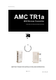
User manual-amc TR1a_G AMC TR1a WiFi Wireless Transmitter with Video On Demand and Broadcasting AMC TM HOME IA Entertainment Center INSTRUCTIONS FOR INSTALLATION AND OPERATION Page 1 of 17 PN: 21-TR1a_IM
User manual-amc TR1a_G Page 2 of 17 PN: 21-TR1a_IM
User manual-amc TR1a_G APPLICATION AND FEATURE LIST FEATURES OF THE AMCTM MODEL TR1a • • • • • • • • • with Video on Demand and Broadcasting features. Wireless IEEE 802.11a 5 GHz Wifi configuration. Internal NTSC / PAL or SECAM / PAL dual band TV Tuner Multiple audio and video inputs supported. Three external Video Inputs : S VIDEO input : one S connector AV1 input: Composite Video(three RCA Connectors- Video, L & R) AV2 input: Composite Video( one 3.
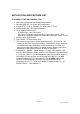
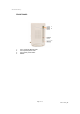
User manual-amc TR1a_G REAR & FRONT SIDE PANELS / FRONT PANEL REAR & FRONT SIDE PANELS Rear Side Panel 10 1. 2. 3. 4. 5. “RJ-45” “DC 12V” power input connector “OFF/ON” Power Switch “S VIDEO” input connector “AV1” Composite Video input RCA connector (Yellow) 6. “AV1” Audio L input RCA connector (White) 7. “AV1” Audio R input RCA connector (Red) 8. “AV2” Composite Video input 3.5mm mini connector(Video, L, R) 9. “TV Tuner” input connector 10.
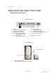
User manual-amc TR1a_G FRONT PANEL 1 2 3 4 1. 2. 3. 4.
User manual-amc TR1a_G REAR SIDE PANEL 1. RJ-45 The RJ45 is for updating firmware of TR1a or hooking TR1a to Ethernet Network for Linking TR1a to all other equipment with IP addresses linked to the Ethernet Network. 2. “DC 12V” power input connector This DC 12V power input connector is for connecting 12VDC power from TR1a Power Adaptor to the TR1a. 3. “OFF / ON” Power Switch Slide the switch to left hand side will turn the power of TR1a OFF.
User manual-amc TR1a_G FRONT SIDE PANEL 1. Connector for IR Blaster The 3.5mm mini connector is for IR Blaster Output. IR Blasters can be hooked up to the connector. 2. Connector for Stereo Audio Pre-Out (Option) The 3.5mm mini connector is for Stereo Audio Pre-Out. The Pre-Out is for connecting to external Stereo Audio systems and the latency between the Pre-Out and Video will have to be adjusted by time delay module.
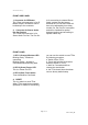
User manual-amc TR1a_G Remote Control (for using with receiving units like AMC i-M15a to control TR1a through IR receiver on receiving units and WiFi ) AMC Page 8 of 17 PN: 21-TR1a_IM
User manual-amc TR1a_G Function of each button on Remote Control Handset: 1. Power 2. Rescan 3. Video 4. TV 5. Audio 6. Screen 7. ▲ ▼ Menu ► ◄ 8. Mute 9. Saving 10. Display 11. 1~9 12. Volume ▲ 13. Volume ▼ 14. Channel ▲ 15. 100 16. 0 17. ◄ 18. Channel ▼ 19. TV Scan 20. Wireless 21. Bitrate 22. Enter On/Off for receiver to re-scan and locate all available TR1a and can select one preferable TR1a.
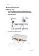
User manual-amc TR1a_G SETUP and INSTALLATION Installing the TR1a z For the best reception of the wireless signal to all areas of your house, it is best to install the TR1a near the center of your house. z TR1a setup overview z Connecting source devices to TR1a 1.
User manual-amc TR1a_G 2. Connect source devices to “S-Video”, “AV-1” and “AV-2” input connectors on rear side panel of TR1a Use S-Video cable included in TR1a to connect your source device with S-Video output to the S Video input connector of TR1a. Use 3 RCA plug to 3 RCA plug Composite AV cable (Yellow for Video, White for Audio-L, Red for Audio-R) included in TR1a to connect your source device like DVD Player with Composite outputs to the AV1 inputs of TR1a. Use 3 RCA plug to 3.
User manual-amc TR1a_G Installing the corresponding receivers like i-M15a (here we use i-M15a for the installing procedures ) 1. Turn on TR1a – power LED will be lighted 2. Turn i-M15a (or other corresponding receivers) battery power ON by pressing the POWER (Battery Power) button on top of i-M15a for 5 seconds. Once i-M15a battery power turning ON i-M15a will be under Standby mode. (If you have power adaptor plugged into i-M15a, the i-M15a will be under Standby mode all the time. 3.
User manual-amc TR1a_G 9. When one i-M15a selected a TR1a and other i-M15a's want to connect to the same TR1a, the other i-M15a's will be under LISTENING mode. And the TR1a will be only controlled by the 1st i-M15a connected to it. 10. Scanning in TV Channels a. Press the TV button on the remote to select between “Broadcast TV” and “Cable TV” b. Press TV SCAN button on the remote and choose your local TV system by pressing “TV SCAN” button in sequence. c.
User manual-amc TR1a_G Page 14 of 17 PN: 21-TR1a_IM
User manual-amc TR1a_G SPECIFICATIONS Wireless ............... IEEE 802.11a 5 GHz Video Encoder ..... MPEG2 video chip, DVD Quality Video Scaler ........ 3D video image chip with Video on Demand and Broadcasting features Wireless IEEE 802.11a 5 GHz Wifi configuration Internal NTSC / PAL or SECAM / PAL dual band TV Tuner Three external Video Inputs : S VIDEO input : one S connector AV1 input: Composite Video(three RCA Connectors- Video, L & R) AV2 input: Composite Video( one 3.
User manual-amc TR1a_G Page 16 of 17 PN: 21-TR1a_IM
User manual-amc TR1a_G WELTRONICS CORP. LONDON/L.A. AMC Web: http://www.amchome.