PN 720-0158-00 March 2007 Installation Guide 3ware® 9650SE Serial ATA RAID Controller
Copyright ©2004-2007 Applied Micro Circuits Corporation (AMCC). All rights reserved. This publication may be copied or reproduced for reference purposes only. All other purposes require the express written consent of AMCC, 215 Moffett Park Drive, Sunnyvale, CA 94089. AMCC shall not be responsible or liable for, and shall be held harmless against, any and all damages, claims, and/or disputes that arise from the copying or reproduction of this publication.
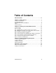
Table of Contents About this Guide . . . . . . . . . . . . . . . . . . . . . . . . . . . . . . . . . . . . .iv Chapter 1. Getting Started . . . . . . . . . . . . . . . . . . . . . . . . . . . . . 1 Contents of this Package . . . . . . . . . . . . . . . . . . . . . . . . . . . . . . . . . . . . . . 1 System Requirements . . . . . . . . . . . . . . . . . . . . . . . . . . . . . . . . . . . . . . . . 2 9650SE RAID Controller Card Models. . . . . . . . . . . . . . . . . . . . . . . . . . . . 4 Cables . . . . .
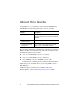
About this Guide Congratulations on your purchase of the 3ware® 9650SE Serial ATA RAID Controller. This guide tells you how to install it.
Chapter 1.
Chapter 1. Getting Started For the 4-port, 8-port, 12-port, and 16-port models, Multi-lane™ break-out cables (SFF-8087) are provided, for use with individual drives. Each of these Multi-lane cables supports up to four serial ATA drives. One is provided with the 4-port controller Two are provided with the 8-port controller Three are provided with the 12-port controller Four are provided with the 16-port controller Note: For the 4-port, 8-port, 12-port, and 16-port models.
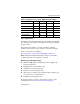
System Requirements Table 1: Required Slots for 3ware RAID Controller Models Controller Model PCI-E X1 PCI-E X4 PCI-E X8 PCI-E x16 9650SE-2LP Yes Yes Yes Yes 9650SE-4LPML No Yes Yes Yes 9650SE-8LPML No Yes Yes Yes 9650SE-12LPML No No Yes Yes 9650SE-16LPML No No Yes Yes 9650SE-24M8 No No Yes Yes Drive Requirements Depending on the particular model, the 3ware RAID controller may be connected to up to twenty-four SATA drives using the supplied interface cables.
Chapter 1. Getting Started Other Requirements Adequate air flow and cooling Adequate power supply for drives 3DM 2 (3ware Disk Manager), a browser-based application used to configure and maintain RAID units, requires one of the following browsers: Internet Explorer 5.5 and later Mozilla Firefox 1.2 and later Netscape 7 and later Konquerer 3.5.
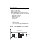
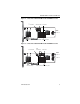
650SE RAID Controller Card Models Figure 2. 4-Port 3ware 9650SE-4LPML Serial ATA RAID Controller I2C connector LED Connector Heat Sink Ports: 0 thru 3 Slots for battery holder BBU connector and hole for post Figure 3. 8-Port 3ware 9650SE-8LPML Serial ATA RAID Controller I2C connector LED Connectors Heat Sink Ports: 4 thru 7 0 thru 3 Slots for battery www.3ware.
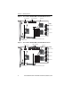
Chapter 1. Getting Started Figure 4. 12-Port 3ware 9650SE-12ML Serial ATA RAID Controller I2C connector LED Connectors Heat sink Ports: 8 thru 11 4 thru 7 0 thru 3 Holes for battery holder BBU connector and hole for post Figure 5.
Cables Figure 6. 24-Port 3ware 9650SE-24M8 Serial ATA RAID Controller I2C connector LED Connectors Heat sink Ports: 16 thru 23 8 thru 15 0 thru 7 Holes for battery holder BBU connector and hole for post Cables SATA Cables The 2-port 9650SE RAID controller uses standard SATA cables. Multi-lane Cables Important: You should only use AMCC/3ware certified cables with your 3ware RAID controller. Using an incorrect cable can result in drives that are not detected.
Chapter 1. Getting Started Multi-lane breakout cables for 4-port, 8-port, 12-port, and 16-port ML controllers For use with a backplane that has individual SATA connectors or individual serial ATA drives, Multi-lane breakout cables have an SFF-8087 Multi-lane connector on one end and four individual SATA connectors on the other end (Figure 7). Note: This is the type of cable that ships with most 3ware 9650SE Multi-lane controllers (except the 24-port).
Cables Multi-lane M8 Y cable Use this cable when connecting a 9650SE-24M8 controller to multi-lane-enabled drive backplanes that have SFF-8087 mini SAS 4i connectors (Figure 9). Figure 9. Multi-lane M8 Cable (SFF-8087) Multi-lane M8 fanout cable When connecting a 9650SE-24M8 controller to individual SATA drives or a backplane that has individual SATA connectors, use the Multi-lane M8 fanout cable. These cables have an M8 connector on one end and eight individual SATA connectors on the other end.
Chapter 1. Getting Started Multi-lane converter cables for 4-port, 8-port, 12-port, and 16-port controllers To connect from a 3ware 9650SE multi-lane RAID controller to a chassis that has SFF-8470 connectors on the backplane, use multi-lane converter cables, which have a SFF-8087 connector on one end and an Infini-band SFF-8470 connector on the other (Figure 10). Figure 10.
Safety Information Well-ventilated and away from sources of heat including direct sunlight and radiators. Away from sources of vibration or physical shock. Isolated from strong electromagnetic fields produced by electrical devices. In regions that are susceptible to electrical storms, we recommend you plug your system into a surge suppressor or UPS (uninterruptible power supply). During an electrical storm, we recommend disconnecting all phone, network, and power cables.
Chapter 1. Getting Started ESD (Electrostatic Discharge) Precautions To avoid damaging computer components and accessories when installing or removing the 3ware RAID controller, follow standard electrostatic discharge (ESD) precautions: When your computer case is open and its internal parts are exposed, do not touch any internal part unnecessarily. Always wear a grounded strap or work on an ESD-protective mat.
Safety Information Note: Some low-cost motherboards have a single PCI Express slot which is reserved for a video card. These slots cannot accommodate a 9650SE RAID controller or other PCI-E device. Warning! Do NOT insert the 9650SE controller into a PCI-X slot. Doing so could potentially damage the board or the system, and void the warranty.
Chapter 1. Getting Started Drive Installation Considerations Selecting an enclosure. If you are planning to use RAID 1, 5, 6, 10, or 50, you may want to consider installing drives into hot-swappable enclosures, so that they can be easily removed in the event of a drive failure. For a discussion of RAID levels, see the 3ware Serial ATA RAID Controller User Guide. When to install the drives.
Chapter 2. Installing Your 3ware RAID Controller Tools You Need You will need the following tools during installation: An ESD grounding strap or mat A Phillips screwdriver Before You Start 3ware 9650SE RAID controllers can be installed in a standard enclosure or in an enclosure with a backplane. 1 Be sure to read “Safety Information” on page 10 in Chapter 1. 2 If you have a Battery Backup Unit (BBU), install it on the controller before proceeding. For details, see “Chapter 3.
Chapter 2. Installing Your 3ware RAID Controller Step 1 (9650SE-2LP). Connect the Cables to the Controller 1 For the 9650SE-2LP, take out the SATA cables provided with the controller. (For other 9650SE models, turn to the next page.) One edge of each SATA cable connector is keyed so that it can only be inserted in one direction. This helps to ensure proper orientation and installation 2 Decide to which port you want to connect the first cable.
Step 1 (Multi-lane Controllers). Connect the Cables to the Controller Step 1 (Multi-lane Controllers). Connect the Cables to the Controller The 9650SE-4LPML, 9650SE-8LPML, 9650SE-12ML, 9650SE16ML, and 9650SE-24M8 models are all multi-lane controllers. (For the 9650SE-2LP, turn to the previous page.) 1 Take out the multi-lane cables provided with your controller. 2 Connect each multi-lane cable to a multi-lane connector on the controller.
Chapter 2. Installing Your 3ware RAID Controller Step 2. Install the Controller in the Computer 1 If the computer is running, shut it down. Turn off power to the computer and disconnect the power cord from the outlet. 2 Make sure you are properly grounded. (For details about safety precautions, see page 10.) 3 Open the computer case according to the manufacturer’s instructions. 4 Find the PCI Express slot you want to use for the 3ware 9650SE RAID controller.
Step 2. Install the Controller in the Computer 7 Press down gently on the edge of the 3ware RAID controller directly above the PCI Express slot until it is fully seated. Figure 13. Inserting Controller Into PCI Express Slot Use a PCI Express slot for the 3ware 9650SE controller. Do NOT use a PCI or PCI-X slot. If in doubt about what slots you have, check the documentation for your motherboard.
Chapter 2. Installing Your 3ware RAID Controller Step 3. Connect the Cables to the Drives Note: The steps on this page apply if you are connecting your controller to individual drives. If you are connecting to Multi-lane drive backplanes, follow the steps on the next page. 1 If your drives are not already installed in the computer chassis or hot swap carriers, install them now. 2 For each drive, select the end of a SATA cable and plug it into the drive or drive carrier.
Step 3. Connect Cables to the SATA/SAS Drive Multi-Lane Backplane Step 3. Connect Cables to the SATA/ SAS Drive Multi-Lane Backplane Note: The steps on this page apply if you are connecting to a Multi-Lane backplane. If you are connecting to individual drives, follow the steps on the previous page. 1 If your drives are not already installed, install them now by attaching them to the backplane. 2 Connect the other end of each Multi-lane cable to the backplane.
Chapter 2. Installing Your 3ware RAID Controller Figure 15. 2-Port 3ware 9650SE-2LP Serial ATA RAID Controller LED indicators for individual Overall LED drive status indicator: drives on J7: 0 and 1 (left to the last two pins of J7. The anode right) is the lower of the two pins and the cathode is the upper. Figure 16. 4-Port 3ware 9650SE-4LPML Serial ATA RAID Controller Overall LED drive status indicator: LED indicators for individual the last two pins of J7.
Step 4. Connecting Drive Activity LED Indicators (Optional) Figure 17. 8-Port 3ware 9650SE-8LPML Serial ATA RAID Controller LED indicators for individual drives J7 is for drives 0, 1, 2, 3 (left to right) J8 is for drives 4, 5, 6, 7 (left to right) Overall LED drive status indicator is the right-most LED header pin pair on each LED connector (J7 and J8). The anode is the lower of the two pins and the cathode is the upper. Figure 18.
Chapter 2. Installing Your 3ware RAID Controller Figure 19. 16-Port 3ware 9650SE-16ML Serial ATA RAID Controller LED indicators for individual drives J7 is for drives 0, 1, 2, 3 (left to right) J8 is for drives 4, 5, 6, 7 (left to right) J9 is for drives 8, 9, 10, 11 (left to right) J1 is for drives 12, 13, 14, 15 (left to right) 24 Overall LED drive status indicator is the right-most LED header pin pair on each LED connector (J7, J8, J9, J1).
Step 4. Connecting Drive Activity LED Indicators (Optional) Figure 20.
Chapter 2.
Step 4.
Chapter 2. Installing Your 3ware RAID Controller Table 2: LED Indicator Pin Positions Controller LED Header J14 Pin Pair Comment : : : : : Orientation Horizontal 20 21 22 23 All Port number/All (all activity indicator) k-cathode-minus is on the top a-anode-plus is on the bottom Warning: If using a chassis that has a common or shared LED ground, be sure to only connect LED cables to the anode pins on the controller. Do not connect any common ground to any cathode pins on the controller. Step 5.
Chapter 3. Installing the Battery Backup Unit The Battery Backup Unit (BBU) is an add-on that can be attached to a 3ware 9650SE RAID controller to supply power to the memory module from an attached battery pack in the event of a system power loss. This allows the controller to use write-caching for optimal performance and not be exposed to data loss in the event of a system power failure.
Chapter 3. Installing the Battery Backup Unit Note: The battery will drain if it is plugged into the BBU and there is no power to the unit. Wait to plug the battery into the BBU until the system is ready for use. Tools and equipment required Slot-head screwdriver Grounding strap Battery Backup Unit (BBU) and battery 3ware 9650SE series controller Installation Overview The Battery Backup Unit (BBU) is comprised of two pieces: the battery module and the BBU control module.
Installation Overview Figure 22. Points of connection on the half-height controller a) Slots for the clips b) BBU receptacle c) Hole for post Figure 23. Points of connection on the full-height controller a) Hole and slots for the clips www.3ware.
Chapter 3. Installing the Battery Backup Unit Installation Instructions 1 Remove the screw head from the plastic post on the BBU control module and set it aside (you will reattach it soon.) Figure 24. Removing the head from the plastic post 2 Position the BBU control module above the controller and align the BBU control module and the controller, making sure to: Mate the connector on the BBU control module with the receptacle on the controller.
Installation Instructions 3 Press down gently until the BBU is seated. Figure 26. BBU control module connected to the controller 4 Turn the controller over, insert the plastic screw head that you removed in step 1 into the plastic post, and tighten it gently but firmly. (Do not over-tighten!) Warning! To avoid possible damage to the controller and the motherboard, make sure the module is connected in the proper orientation, and that the plastic post is attached.
Chapter 3. Installing the Battery Backup Unit 5 If you have a 4-port or 8-port 9650SE: a Hook the clips on the top of the battery module over the slots on the top edge of the controller. Figure 27. Clips on the battery module hook over slots on the top edge of the half-height controller Figure 28.
Installation Instructions b Press down gently on the top of the battery unit so that the battery holder flexes slightly and the clip on the bottom slips over the slot on the bottom edge of the controller. Figure 29. Pressing down gently so that the bottom clip can be inserted Bottom clip If you have a 12-port, 16-port, or 24-port 9650SE: a Insert the clips on the top of the battery module into the holes on the controller. Figure 30.
Chapter 3. Installing the Battery Backup Unit 3 Insert the battery power connector into the power receptacle on the BBU. Note: The battery will drain if it is plugged in and there is no power to the unit. If the system will not be used right away, wait to do this step until the system is ready for use. Figure 31. Battery power connector inserted in power receptacle The controller is now ready to install in your system.
Replacing the Battery Replacing the Battery The Battery Backup Unit (BBU) will last for many years. The battery has an expected life span of one to two years depending on usage. You can check the current status of the battery, and test it. For details, see instructions in 3ware Serial ATA RAID Controller User Guide. Caution: There is a risk of explosion if the battery is replaced by an incorrect type. To obtain a replacement battery module, contact AMCC.
Chapter 3. Installing the Battery Backup Unit 4 5 While pressing down on the top of the battery module, lift out the bottom of the battery module slightly. Once the bottom of the module is free, slide the module up to release the clips on the top. Figure 32. Removing the battery module a) Push the battery module down gently. b) Lift out the bottom of the battery module to release the clip on the bottom edge. Bottom clip 6 38 c) Lift up to remove the clips on the top edge.
Replacing the Battery Figure 33 shows how removing the connector looks if you remove the BBU control module from the controller. Figure 33. Removing the power cable from the BBU module Press down on the lever-like clip and pull the connector out. 7 If you removed the BBU control module in step 6, reattach it now. 8 Insert the new battery module and cable it up. 9 Reinstall the 3ware RAID controller, close up your system, and restart it.
Appendix: Technical Support For support, troubleshooting tips, frequently asked questions, software releases, and compatibility information related to 3ware RAID controllers, refer to: 3ware support page at: http://www.3ware.com/support/ 3ware knowledgebase: http://www.3ware.com/KB/kb.asp 3ware software downloads: http://www.3ware.com/support/download.asp 3ware documentation: http://www.3ware.com/support/userdocs.asp 3ware Compatibility Lists: http://www.3ware.