Digital Video Recorder User Manual Version 1.0.
Contents Contents.........................................................................................................................................................................2 Welcome ........................................................................................................................................................................6 1. Features and Specification.....................................................................................................................
4.3.5. Snapshot ............................................................................................................................................................26 4.3.6. Basic ...................................................................................................................................................................27 4.3.7. Record ................................................................................................................................................
6.1.2. Encode ...............................................................................................................................................................73 6.1.3. Overlay ...............................................................................................................................................................76 6.1.4. PTZ ....................................................................................................................................................
6.5.3. ONVIF User.......................................................................................................................................................126 6.6. Info ......................................................................................................................................................................127 6.6.1. Version .................................................................................................................................................
Welcome Thank you for purchasing an Amcrest DVR! This user manual is designed to be a reference tool for the installation and operation of your DVR system. Here you can find information about the DVR’s features and functions, as well as information to aid in troubleshooting. Many of the setup and installation sections below have corresponding videos on YouTube To access the setup videos, please go to http://amcrest.com/videos NOTE: This user manual is applicable to all Amcerst XVR/H5 model DVRs.
The product must be grounded to reduce the risk of electric shock. We assume no liability or responsibility for any fires or electrical shock caused by improper handling or installation. 2.Transportation Security Heavy stress, violent vibrations, and excess moisture should not occur during transportation, storage, and installation of the DVR. 3.Installation Handle the DVR with care. Keep the DVR right side up. Do not apply power to the DVR before completing installation.
1.2 Features The Amcrest has the following features: • Real-time Monitoring The has an analog output port, VGA port, and an HDMI port. You can use a variety of monitors to display the DVR’s interface, and the DVR can support VGA and HDMI output at the same time. • Storage Functionality The DVR can record multiple video and audio streams to the built-in hard drive to allow for playback of any recorded media.
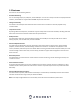
2. Overview and Controls This section provides information about the physical design and controls for the DVR. Please refer to the diagrams below to become acquainted with the DVR and its physical features. 2.1 Front Panel Port Name Function 1 HDD Glows blue when HDD status is abnormal. 2 NET Glows blue when network status is abnormal. 3 POWER Glows blue when the power is connected properly. 4 USB Port Connects to external DVRs such as a mouse or USB storage DVR 2.
Port Name Function 4 HDMI port High definition audio and video signal output port. The port outputs an uncompressed high-definition feed as well as multi-channel audio data to a connected HDMI compatible display. 5 Network port Connects to Ethernet port. 6 USB port 7 VGA port 8 Power input port Connects to an external DVR such as, a mouse, keyboard, or external USB storage DVR. Outputs analog video data to a connected display with a compatible VGA port. 9 10 Inputs DC 12V power.
Right click mouse In real-time monitor mode, pops up shortcut menu: one-window, four-window, nine window and sixteen-window, Pan/Tilt/Zoom, color setting, search, record, alarm input, alarm output, main menu. Among which Pan/Tilt/Zoom and color setting applies for current selected channel. If you are in multiple-window mode, system automatically switches to the corresponding channel. Exit current menu without saving the modification.
1. Loosen the screws of the upper cover and side panel. 2. Attach four screws in the HDD (Turn three times). 3. Place the HDD in accordance with the four holes on the bottom. 4. Connect the HDD power and data cable to the motherboard of the unit. 5. Secure the HDD to the unit by tightening the four screws. 6. Place the upper cover back on the unit and secure it to the unit. Note: • An HDD is NOT included with the DVR by default.
The input video signal should have high SNR, low distortion; low interference, natural color and suitable brightness. To guarantee the stability and reliability of the camera signal, the camera should be installed in a cool, dry place away from direct sunlight, flammable materials, explosive substances, etc. The camera and the DVR should have the same grounding to ensure the normal operation of the camera.
The audio output signal parameter is usually over 200mv 1KΩ (BNC or RCA). It can directly connect to a low impedance earphone, active speaker, or amplifier-drive audio output DVR. • • • If the speaker and the microphone cannot be separated spatially, it may create a feedback loop. In this case you can adopt the following measures: Use a better directional microphone. Reduce the volume of the speaker.
2. Connect the included USB mouse to the front of the DVR. 3. Connect an Ethernet cable to your router. 4. Then, connect the other end of the Ethernet cable to the DVR.
5. Secure the coaxial extension cable to the camera’s video cable port. Then, connect a power adapter to the camera’s power adapter port and plug the power adapter into a wall socket or power source. 6. Secure the coaxial cable port from the camera to any of the video (coaxial) ports on the back of the DVR. 7. Connect the power adapter into the back of the DVR, and then plug in the DVR power adapter into an electrical socket to turn on the unit.
3.4.1. Using an Amcrest 4-in-1 Camera Quadbrid or 4-in-1 technology, allows for a flexible means of providing HD-CVI, HD-TVI, AHD, and Analog formatted video to your DVR. The signal is transmitted uncompressed, which eliminates latency and allows for real-time, highly reliable video security without loss or delay. The cameras connect point-to-point directly to the DVR (BNC) which provides a highly secure, closed network, as well as a painless and non-complex plug-and-play setup process.
Step 1: Connect a BNC (coaxial) cable to the video out connection of your camera. Step 2: Connect the male end of the DC power connector of the BNC (coaxial) cable to the female end of the power connector of the camera. Step 3: Connect the BNC (coaxial) cable to a video out channel on the back of your DVR. Step 4: Connect the male end of the DC power connector of the power adapter to the female end of the power connector of the BNC (coaxial) cable. Plug in the power adapter to apply power to the camera.
To factory reset the DVR, unplug the DVR from power. Once power is removed from the unit, press and hold the factory reset switch for 4 - 5 seconds. Continue holding the reset switch and plug the DVR's power supply back into the unit, you will hear a beep. Continue holding the reset switch and allow the DVR to initialize for 20 - 30 seconds and then release the switch. The DVR will be set to default and will show the DVR initialization screen.
4.1.2 Shut down • • Click the logout button located on the main menu and select Shut Down. Do not unplug the power cable or click the power on-off button to shut down the DVR directly when DVR is running (especially when it is recording.) 4.2. DVR Initialization In this screen you will be able to enable DVR initialization features. These are basic features related to the system, such as password setups, recovery settings, etc. 4.2.
• If the password for the administrator account is misplaced, forgotten, or a user is locked out, contact Amcrest Support via one of the following options as a hard password reset may be needed: Visit http://amcrest.com/contacts and use the email form o Call Amcrest Support using one of the following numbers Toll Free: (888) 212-7538 International Callers (Outside of US): +1-713-893-8956 USA: 713-893-8956 Canada: 437-888-0177 UK: 203-769-2757 Email Amcrest Customer Support support@amcrest.com 4.2.2.
Next, you will need to assign security questions. These are an added security feature that will help you obtain your password. To begin, select a question from the drop-down menus for Question 1, Question 2, and Question 3 and enter the answers to those questions in the Answer fields. Once this section is complete, click on the Save button to save your information and move on to the next initialization screen. 4.3 DVR Setup 4.3.1.
4.3.2. Date&Time The next screen that appears will be the Date & Time settings screen. This is where you can set the date and time for your specific location. If you wish to utilize daylight savings time, toggle the DST toggle switch to the on position. Once you have selected the proper date and time for your DVR, click the Next button to continue. Note: Make sure to toggle the NTP toggle switch to the off position to avoid syncing your DVR to the NTP server.
4.3.3. Network The next screen that will appear is the Network settings screen. In this screen you can configure the network settings. If you want to set your DVR up to have a static IP, toggle the DHCP toggle switch to the off position. Note: To test the connectivity of the DVR to your network, click on the Test button. The DVR will return a network status. To return to the previous menu, click the Back button.
4.3.4. P2P The next screen that appears is the P2P settings screen. It is highly recommended to keep this enabled if you want to use the DVR in the Amcrest View Pro mobile app or AmcrestView.com so you can view your DVR remotely on your mobile device. On this screen you will notice two QR codes. These QR codes allow you to download the cell phone client (Amcrest View Pro) app as well as quick access to your DVR’s serial number.
If you have made any incorrect encode settings and would like to revert the settings back to its original default settings, click on the Default button. You can also copy and apply the settings to multiple channels if they apply. To copy the encode settings to multiple channels press the Copy button and select which channels you would like the settings to apply with. To return to the previous menu, click the Back button.
If you have made any incorrect settings and would like to revert the settings back to its original default settings, click on the Default button. You can also copy and apply the settings to multiple channels if they apply. To copy the encode settings to multiple channels press the Copy button and select which channels you would like the settings to apply with. To return to the previous menu, click the Back button.
4.3.7. Record The next screen you see is the Record settings screen. Your DVR is configured, by default, to record everything on all channels 24/7 (this will only actually happen provided you have a hard drive installed). You can also use this screen to set up motion detection and alarm schedules. If you have made any incorrect settings and would like to revert the settings back to its original default settings, click on the Default button.
Once the setup process is finished and you have clicked the “Finished” button, you should see the below dialog box: Click OK to continue and the next screen you will reach will be the home video wall screen for your system. 4.4. Live View When you have completed initial setup of the DVR, you will notice a video wall. The video wall will display all live connected cameras, excluding IP cameras. Note: The number of screens displayed will be dependent on the model of your DVR. 4.4.1.
corner represents the channel number. If the channel position is changed or the name is modified, you can recognize the channel number by this figure. This number also represents the channel number you will refer to for performing operations such as, record queries, and playback. For more information on the icons listed, refer to the table below. Icon Function Indicates recording status. This icon displays when the video is being recorded. This icon displays when the motion detection occurs in the scene.
No. Function No. Function No. 1 Instant Play 4 Manual Snap 7 2 Digital Zoom 5 Mute 3 Real-time Backup 6 Audio Talk Function Camera Registration 4.4.2. Instant Playback This option allows you to play back the previous five to sixty minutes of a recorded video. By clicking on the follow features: ⚫ ⚫ ⚫ ⚫ icon, the instant playback interface will be displayed. The instant playback feature has the Move the slider to choose the time you want to start playing. Play, pause and close playback.
4.4.3. Digital Zoom This feature allows you to enlarge a specific area of the image in the live view screen. This function can be accessed in two ways: ⚫ ⚫ Click , the icon switches to . Hold down the left mouse button to select an area you want to enlarge. The area is enlarged after the left mouse button is released. Point to the center that you want to enlarge, rotate the wheel button to enlarge the area.
You can mute the video sound by clicking . This function is supported in single-channel view.\ 4.4.6. Bidirectional Talk This feature is only available in digital channels. You can perform the voice interaction between the DVR and other remote DVR to improve efficiency. This function is supported only when the remotely connected IPC DVR supports bidirectional talk. ⚫ Click , the icon switches to , the bidirectional talk of the remote DVR is turned on.
Icon Function Open the EVENT interface to view the DVR alarm status. Open the CHANNEL INFO interface to display the information of each channel. Open the CAMERA REGISTRATION interface. Open the NETWORK interface. Open the HDD MANAGER interface. Open the USB MANAGER interface. Open the UPGRADE MANAGER to make sure your system is operating on the latest firmware. 4.
Function Next Screen Camera Registration Manual Preview Mode Description Click the Previous Screen button to go to the previous screen. For example, if you are using 4-split mode, the first screen is displaying the channel 1-4, click Next screen, you can view channel 5-8. Open the CAMERA REGISTRATION interface. Select Record, you can configure the recording mode as Auto or Manual or stop the recording.
No. Icon 1 Function tiles 2 Management menu 3 Live Description Includes five function tiles: VIDEO, ALARM, BACKUP, DISPLAY, and AUDIO. Click each tile to open the configuration interface of the tile. VIDEO: Search for and play back the recorded video saved on the DVR. ALARM: Search for alarm information and configure alarm event actions. BACKUP: Search and back up the video files to the local PC or external storage DVR such as USB storage DVR.
No. 1 2 Function Description Display the searched recorded video or picture. It supports playing in single-channel, 4-channel, 9-channel, and 16-channel simultaneously. Display Window Note: When playing back a recording in single channel mode, hold down the left mouse button to select the area that you want to enlarge. The area is enlarged after the left mouse button is released. To exit the enlarged image, right-click on the image. Playback Controls Bar Playback control buttons.
No. Function Description 4 5 Play Status 6 7 8 Record type Search type Sync Click the date that you want to search, the time bar displays the corresponding record. Calendar 9 View Layout and Channel Selection 10 11 12 For some models, when you are clicking on the blank area in the time bar, the system automatically jumps to the next time point where there is a recorded video located. Includes two playback statuses: Play and Stop.
Icon Function Stop. During playing back, you can click the Stop button to stop playback. Play Backward. During playing back, click the Play Backward button to backward play the recorded video, the button switches to backward. , ; click to stop playing During playing back, click to start playing forward. Previous Frame/Next Frame. When the playback is paused, click recorded video. , or click to play single-frame When playing back single-frame recorded video, click forward. Slow Playback.
Selecting a Search Type This menu is in the upper right-hand corner screen of the playback interface. In this menu you can search for, recorded videos, spliced videos, or snapshots from the installed hard drive or external storage DVR. • From R/W HDD: Recorded videos or snapshots playback from HDD of the DVR. • From I/O DVR: Recorded videos playback from external storage DVR. To access the recorded event and play it back, you can double-click on the video file, or click the playing the video.
In the backup dialog box, click on Backup to begin backing up the selected files to an external USB storage DVR. Note: If you do not want to back up the file, click on the Clear button to return to the previous menu. Smart Search The Smart Search feature enables searching for motion within the recorded file for a specific channel. This feature is useful, as it allows users to search a channel’s recorded files for motion without having to change the recording type to a motion detection recording.
• The system supports 396(22*18 PAL) and 330(22*15 NTSC) zones. Please left click mouse to select smart search zones. Marking and Playing Back Video In this DVR you can mark recordings. This option is useful for areas you want to highlight or refer to when playing back a file. To begin marking a file, select the be displayed. icon located in the playback interface. The Add Mark dialog box will then In the Name field of the dialog box, enter a name for the mark and then click OK.
In the mark list interface, double-click the file that you want to play back. If you need to search for the marked video by time, enter the time of the file in the SEARCH box at the top of the interface and click on the icon. The mark list interface also allows you to play the video in N seconds, or time before the marked time. To begin, enter the name of the marked video in the Name box. Then, in the Playback time before mark box, enter N seconds and click on the marked time. icon to begin playback.
Channel list and select the channel number you wish to access. Then, from the Calendar area, select a date, and click on the icon to allow the system to play. All snapshots related to that specific channel will be played at the configured intervals. Playing Back Splices To playback spliced events via the playback interface, navigate to the Search Type field of the interface located in the upper right-hand corner and select Splice Playback from the drop-down menu.
Note: A maximum of 128 files can be displayed in this menu. File types are listed as, R for general recordings; A for videos with external alarms; M for motion events; and I for intel events. To start playing back a file from the file list, select the file you wish to play from the list and click on the icon located above the time bar. In the search box, you can also enter a specific time of a file to view a file from a specific time. To return to the playback interface, click on the icon.
4.8.2. Alarm The alarm function tile located in the main menu of the DVR allows you to search live alarm information as well as configure alarm action events. Alarm Info This feature allows you to search for specific types of alarm information related to the system. These specific types of alarms include, Motion Detection, Video Loss, Tampering, Abnormalities, Local Alarms, Intel, etc. You can also select All to view all log and alarm information.
To use this feature, access the alarm info interface and select the type of alarm you are search for from the dropdown menu. Enter in the start and end times in the Start Time and End Time fields and click Search. The alarm you are viewing will be accessible via the alarm info list. In this list you can view information such as, the log time, event type and playback. To playback the event, click on the playback icon. If you require to back up any alarm events, the alarm info interface has a backup option.
Motion Detect When a moving object appears or moves fast enough to reach the preset sensitivity values, the system will activate an alarm. These alarms are known as motion detect, or MD. To configure the motion detection settings on your DVR, select the Motion Detect tab in the Video Detect menu and toggle the Enable MD switch to the on position. For a more detailed overview of the motion detect screen, refer to the table provided below.
Parameter Description Click Setting to display setting interface. General Alarm: Enable alarm activation through the alarm DVRs connected to the selected output port. External Alarm: Enable alarm activation through the connected alarm box. Wireless Siren: Enable alarm activation through DVRs connected by USB gateway or camera gateway. Set a length of time that will delay turning off alarms after the external alarm is cancelled.
After you have enabled your desired settings for motion detection, make sure to click the Apply button to save them to your DVR. Note: Click the Default button to restore the motion detection settings to its default setting. To apply the settings to multiple channels on your DVR, click Copy and in the Copy dialog box, select the additional channel(s) you would like to set, and press Apply. To test the applied settings, click the Test button in the motion detect menu.
In this menu, you will define the motion detection period for the selected channel. By default, it is it is active to record motion 24/7. You can define the period, or schedule. • Define a period for a specified day of the week by clicking the half-hour clocks you wish to enable. • Define several days of the week by clicking the the • • icon which indicates it is linked. Define for all days of the week by clicking on the to the icon before each day.
In the period interface, enter the time frame you would like to set as your period and select the checkbox to enable the settings. There are a total of six periods that you can set for each day. Under the Copy menu, you can apply these settings to all days of the week by checking the All option or you can also select specific days as well. To save the settings in this menu, click OK to continue. • Once you have set your desired settings in the Motion Detect interface, click Apply to complete the process.
Parameter Description Set a length of time for the DVR to delay turning off alarm after the external alarm is cancelled. The value ranges from 0 seconds to 300 seconds, and the default value is 10 seconds. If you enter 0, there will be no delay. Select the Show Message check box to enable a pop-up message in your local host PC. Select the Send Email check box to enable the system to send an email notification when an alarm event occurs.
Below is a description of the fields on the Tampering settings page: • Enable: This checkbox allows the user to enable the motion detection function for a specific channel. To select a channel, click on the drop-down menu provided on the right. • Sensitivity – Allows the user to set a preset sensitivity setting for motion detected events. • Period: This setup button takes the user to the tampering period settings screen. Below is a screenshot of the motion detection period settings screen.
In the period interface, enter the time frame you would like to set as your period and select the checkbox to enable the settings. There are a total of six periods that you can set for each day. Under the Copy menu, you can apply these settings to all days of the week by checking the All option or you can also select specific days as well. To save the settings in this menu, click OK to continue. • CAM Anti-Dither: This field allows the user to set the anti-dither time.
• Record Channel: This checkbox allows the user to enable the system to record video for that channel when a motion detection alarm is triggered. Delay is also associated with this tab, it is the This field specifies in seconds how long the delay between alarm activation and recording should be. • PTZ: Allows the user to active PTZ functionality to applicable PTZ DVRs. • Tour: Allows the user to enable the camera to activate a PTZ tour when a motion detection alarm is triggered.
• Rule: This setting allows you to set diagnosis types to specific targets. • Period: This setup button takes the user to the tampering period settings screen. Below is a screenshot of the motion detection period settings screen. In this menu, you will define the tampering period for the selected channel. By default, it is it is active to record 24/7. You can define the period, or schedule. • Define a period for a specified day of the week by clicking the half-hour clocks you wish to enable.
Setting Types of Diagnoses Targets This menu allows you to set the specific features or rules, of the features listed in the diagnosis screen. To set a diagnosis type, click on the Setting button next to the Rule field to access the Diagnosis interface. Select the items that you want to diagnose and set the threshold for these settings. For more information on the settings list in this menu, refer to the table below.
4.8.6. Abnormality This screen is used to specify system actions in the case the device experiences any abnormalities including hard drive, network, or user abnormalities. HDD This screen allows the user to specify actions that occur when there is an abnormality with the DVR’s hard disk drive (HDD).
• Send Email: This checkbox allows the user to enable the system to send an email when an HDD abnormality occurs. • Buzzer: This checkbox allows the user to enable the system to activate a buzzer when an HDD abnormality occurs. • Log: Allows the user to log all motion detected events that are triggered in the DVR. • Voice Prompts (N/A): Allows the user to customize voice prompts for motion detected events. To save settings, click the Apply button.
• Alarm Upload: This checkbox allows the user to enable the system to upload alarm information when a motion detection alarm is triggered. • Send Email: This checkbox allows the user to enable the system to send an email when an abnormality occurs. • Buzzer: This checkbox allows the user to enable the system to activate a buzzer when an abnormality occurs. • Log: Allows the user to log all motion detected events that are triggered in the DVR.
• Voice Prompts (N/A): Allows the user to customize voice prompts for motion detected events. To save settings, click the Apply button. To cancel any modifications, click the Cancel button near the bottom right hand corner. To apply the settings, click the Apply button near the bottom right hand corner. 4.10. Backup The Backup function tile allows you to search and backup data to an external USB storage DVR. The DVR has two USB ports, one in the front and one in the back to utilize this function. 4.10.1.
For a more information on the settings listed in this menu, refer to the table listed below. Parameter Description DVR Name Format In the DVR Name list, select the DVR that you want to back up the files to. Click Format to format the selected DVR. Click Browse, the Browse interface is displayed. Select the route where you want to search for the files. In the Record CH list, select the channel where you want to search for the files. In the Type list, select the file type that you want to search.
For more information on the settings provided in this menu, refer to the table provided below. Parameter Description Main Screen Indicates the main screen port. Select the Time Title check box, the current system time displays in each channel window in live view screen. To hide the time, clear the check box. Select the Channel Title check box, the channel name, channel number and recording status display in each channel window in live view screen. To hide the time, clear the check box.
The view layout configuration can be set by clicking on the layout buttons in the bottom left-corner of the interface. For example, when you click on the immediately as such: icon, which is the 9-16 view layout, the live view layout will change The same concept will apply for the other layout icons listed in the menu. Adjust the position of the channels as needed.
Below is an explanation of the fields on the Tour Setup settings screen: • Enable: This checkbox allows the user to enable the tour functionality. o An alternate way to enable or disable tour is by clicking on the navigation bar. • Interval (Sec): Enter the amount of time that you want each channel group displays on the screen. The value ranges from 5 seconds to 120 seconds, and the default value is 5 seconds.
From the interface, select the channels that you want to group with the established tour settings. Note: If you want to select more than one channel, in the Window Split list, do not select View1. When you have finished selecting the appropriate group order, click OK to complete the process. If you do not wish to proceed with the group function, click Back to exit the add group interface.
In the modify channel group interface, select the group order for your selected group and click OK to complete the process. If you do not want to proceed with the modification, click the Back button to exit the modify group interface. 4.11.4. Zero-Channel This screen is used to configure zero channel encoding functionality. This feature allows for the preview of several channels in one channel’s window.
Parameter Description Enable Enable zero-channel function. In the Compression list, select the video compression standard according to the DVR capability. The default is H.264. In the Resolution list, select the video resolution. The default is 704×576 (D1). Select a value between 1 and 25 for PAL standard, and between 1 and 30 for NTSC standard. The actual arrange is decided and selected dependent on the DVR capability. The default value is 1024Kb/S.
Parameter Period File Name Interval Repeat Output Description In the Period box, enter the time. Select the check box to enable the settings. You can configure up to six periods. In the File Name list, select the audio file that you want to play for this configured period. In the Interval box, enter the time in minutes for how often you want to repeat the playing. Configure how many times you want to repeat the playing in the defined period. Includes two options: MIC and Audio. It is MIC by default.
When the audio file has been imported successfully, you will see the file displayed in the file manager interface: 71
The imported audio files are automatically saved into the HDD, so you do not need to connect to the USB storage device to get the file next time. Click to play the audio file. Click to rename the audio file. Click to delete the audio file. To decrease or increase the playing volume, move the slider to the left or to the right. 6. Management This section of the main menu allows you to access camera, network, storage, system, account, and information directly related to your DVR. 6.1.
Parameter Description Channel In the Channel list, select the channel that you want to configure. In the Cable Type list, select the cable type that the camera uses. Cable Type Period Effective Time Saturation Contrast Brightness Hue Sharpness Image Enhance NR Note: Not all models support this function. In the Period list, select a time period for the image settings. The image settings will be only used during the selected period. Enable the effective function.
For more information on the settings listed in this menu, refer to the table provided below: Parameter Channel Smart Codec Type Compression Resolution Frame Rate (FPS) Quality I Frame Interval Description In the Channel list, select the channel that you want to configure the settings for. Enable the smart codec function. This function can reduce the video bit stream for non-important recorded video to maximize the storage space.
Parameter Description In the Bit Rate list, select a value or enter a customized value to change the image quality. The bigger the value is, the better the image will become. Enable the function for sub stream. Bit Rate (Kb/S) Video Audio Encode Audio Source Click More Setting, the More Setting interface is displayed. Audio Encode: This function is enabled by default for main stream. You need to manually enable it for sub stream 1.
Parameter Manual Snap Channel Mode Image Size Image Quality Interval Description In the Manual Snap list, select how many snapshots you want to take each time. In the Channel list, select the channel that you want to configure the settings for. In the Mode list, you can select Human Face, Event, or General as the event type for which you want to take a snapshot. In the Image Size list, select a value for the image. Configures the image quality by 6 levels.
Parameter Channel Time Display Channel Title Description In the Channel list, select the channel that you want to configure the settings for. Select the Time Display check box to display the system time on each channel window in the live view screen. In the Time Display list, select time display style. Select the Channel Title check box to display the channel name on each channel window in the live view screen. In the Channel Title box, enter the name for the selected channel.
Parameter Channel Preview Record Description In the Channel list, select the channel that you want to configure the settings for. Preview: Select the Preview check box to apply the configured covered block to the selected channel window in the live view screen. Record: Select the Record check box to apply the configured covered block to the selected channel window during recording. To configure covering block, do the following: 1. Select the Preview check box or the Record check box, or select the both.
Parameter Description Channel In the Channel list, select the channel that you want to connect the PTZ camera to. Local: Connect through RS485 port or coaxial cable. Remote: Connect through network by adding IP address of PTZ camera to the DVR. In the Control Mode list, select Serial or . For series product, please select . The control signal is sent to the PTZ through the coaxial cable. For the serial mode, the control signal is sent to the PTZ through the RS485 port.
Parameter Description Speed Controls the movement speed. The bigger the value is, the faster the movement will be. : Wide angle. Zoom : Long shot. : Zoom in. Focus : Zoom out. : Small. Iris : Large. Supports eight directions. Fast positioning button. PTZ movement Positioning: Click to enter the fast positioning screen, and then click anywhere on the live view screen, the PTZ will turn to this point and move it to the middle of the screen.
Note: The functions with buttons that are greyed out will not be supported by the system. To return to live view screen right-click once on the interface. To exit the expanded PTZ control panel, click on the icon. For more information on the settings listed in the expanded PTZ control panel, refer to the table provided below. Icon Function Icon Function Preset Auto Pan Tour Flip Pattern Reset Autoscan Click the AUX Config icon to open the PTZ functions settings interface.
Configuring PTZ Tour The tour function allows for the use of multiple presets stringed together. To access the PTZ tour menu, navigate to the expanded control panel and click on the interface provided, click on the Tour tab. icon. On the PTZ To create and manage tours, follow the steps below: • Ensure you have more than 1 preset configured already. • Input the tour value into the Patrol No. • Click the Add Preset button to add another preset. • Continue adding presets as needed.
To create a pattern, click Begin, then use the PTZ controls to move the camera around. Once finished, click End to end and save the pattern. During the use of pattern mode, zoom/focus/iris cannot be modified. Configuring PTZ Borders The border function allows for constraining the area of movement for the cameras during any PTZ function. To access the PTZ border menu, navigate to the expanded control panel and click on the interface provided, click on the Border tab. icon.
Calling Presets Using the expanded PTZ control panel, enter the value of the preset you wish to call in the No. box. Once you have entered this value, click on the exit. icon to access the preset. To stop calling the preset, click on the icon to Calling Tours Using the expanded PTZ control panel, enter the value of the tour you wish to call in the No. box. Once you have entered this value, click on the icon to access the tour. To stop calling the tour, click on the icon to exit.
⚫ ⚫ In the Direct Aux list, select the option that corresponds to the applied protocol. In the Aux Num box, enter the number that corresponds to the AUX switch on the decoder. 6.1.7. Calling the OSD Menu Using the expanded PTZ control panel, click on the icon to access the Menu Operation interface. To enter the Main Menu of the OSD screen, click on the Enter button in the Main Operation interface. The OSD screen will appear on the live view screen.
6.1.8. Channel Type The channel type menu allows the user to configure specific channels types in the system. These channel types include both Analog and IP channels configurations. Configure the channels. Analog Channel: Select the transmission medium such as CVI, CVBS, and then follow the onscreen instructions to complete the settings. IP Channel: Select a channel for IP camera from the last channel number. Select from the 5-6 check box. Then follow the onscreen instructions to complete the settings.
1. Click on the Camera option located in the Management section of the Main Menu. 2. Click on Channel Type and select the IP Camera option. (This is dependent on how many channels your specific model DVR can handle.) 3. Click on Apply and allow the DVR to reset. 4. Navigate back to the Camera menu and click on Registration. 5. Click on Device Search to search for the IP camera you want to add and click on the enable checkbox. . 6. Click on the Add button to add the IP Camera to the DVR.
6.1.10. Coaxial Upgrade The coaxial upgrade screen provides a means of upgrading firmware, specifically for coaxial cameras. The firmware upgrades in this menu are only related to coaxial connected cameras, not the system itself. Note: Before continuing with the process, ensure to have an external USB storage device connected to the system. The storage device should contain the .bin file for the upgrade. To access the .bin, please visit amcrest.com/firmware and search for your DVR.
6.2.1. TCP/IP TCP/IP stands for Transmission Control Protocol/Internet Protocol and it is the language/protocol that allows communication between internet connected DVRs, whether on a local network, or a on the Internet at large. This screen allows for TCP/IP settings to be modified for the DVR to establish connection to the network.
• MTU: MTU stands for Maximum Transmission Unit. This field allows the user to set the MTU value of the network adapter. The value ranges from 1280-7200 bytes. The default value is 1500 bytes. Please note MTU modification may result in network adapter reboot and the network turning off. That is to say, MTU modification can affect the current network service. The system may pop up a dialog box to confirm setup when the MTU value is changed.
• TCP Port: This field designates the Transmission Control Protocol (TCP) port number. The default value is 37777. • UDP Port: This field designates the User Datagram Protocol (UDP) port number. The default value is 37778. • HTTP Port: This field designates the Hypertext Transfer Protocol (HTTP) port number. The default value is 80. • RTSP Port: This field designates the Real Time Streaming Protocol (RTSP) port number. The default value is 554.
Below is an explanation of the fields that can be configured on DDNS settings screen when set to AMCREST DDNS type. • Enable: This switch allows the user to enable DDNS on the DVR. • DDNS: Type: This dropdown box allows the user to select which DDNS service is being used on the DVR. • Domain Name: This field allows the user to enter the domain name from the AMCREST DDNS service. • MAC Address: The assigned MAC address for the DVR.
For more information about the settings listed in this menu, refer to the table below: Parameter Description Enable SMTP Server Enable the email function. Enter the address of SMTP server of sender’s email account. Enter the port value of SMTP server. The default value setting is 25. You can enter the value according to your actual situation. Port User Name Password Anonymity Mail Receiver Email Address Sender Title Attachment Authentication Interval (Sec.) Health Enable Interval (Min.
After you have enabled the email settings for your DVR, click on the Test button to test the connection. If the email test fails, make sure your Email Account has 2-Step Verification turned off. Confirm your Internet settings on the DVR are configured correctly. 2-Step Verification FAQ Gmail After you login to your Gmail and you can view your inbox open a new tab and go to: https://myaccount.google.
Below is an explanation of the fields in the UPnP settings screen: • PAT: PAT stands for Port Address Translation, and it is something that the UPnP protocol handles. This checkbox allows the user to enable UPnP on the DVR. The settings in PAT table correspond to the UPnP PAT table on the router. ◼ ◼ ◼ ◼ Service Name: Name of network server. Protocol: Type of protocol. Int. Port: Internal port that is mapped on the DVR. Ext. Port: External port that is mapped on the router.
o The third column shows the name of the protocol used by that service. To edit this, double click on the service line item. o The fourth column shows the Internal Port used by that service. To edit this, double click on the service line item. o The fifth column shows the External Port used by that service. To edit this, double click on the service line item. To confirm settings, click the Apply button near the bottom right hand corner.
Well-known IPv6 multicast addresses Address Description ff02::1 All nodes on the local network segment ff02::2 All routers on the local network segment ff02::5 OSPFv3 All SPF routers ff02::6 OSPFv3 All DR routers ff02::8 IS-IS for IPv6 routers ff02::9 RIP routers ff02::a EIGRP routers ff02::d PIM routers ff02::16 MLDv2 reports (defined in RFC 3810) ff02::1:2 All DHCP servers and relay agents on the local network segment (defined in RFC 3315) ff02::1:3 All LLMNR hosts on the local netw
Below is an explanation of the fields on the Register settings screen: • • • • • Enable: This checkbox allows the user to enable the Register feature for the DVR. No: This dropdown box allows the user to select the proxy number. Currently the DVR can only configure one proxy. Server IP Address: This field allows the user to enter the proxy server IP address. Port: This field allows the user to enter the proxy port number. Sub Device ID: This field allows the user to enter the proxy ID number.
To begin, make sure that the Enable switch is in the on position. The status field will then say, Online. When the P2P function is in online status, you can utilize the QR codes listed on the screen: Cell Phone Client: Use your mobile phone to scan the QR code to add the DVR into the Cell Phone Client, and then you can start accessing the DVR. Platform: Obtain the DVR SN by scanning the QR code. Go to the P2P management platform and add the DVR SN into the platform.
1. Access the Amcrest View Pro app from your mobile 2. From the Device Manager screen, you can click on DVR and tap on the icon to display the main menu. From the main menu, click on Device Manager to begin adding the DVR to the application. either Add Device or the hand corner. 3. Next, you will need to select a DVR type from the Select Device Type menu. Since we are adding a DVR to the application, click on the DVR/NVR option at the bottom of the menu. 4.
4. The app will then prompt you to scan the QR code for your DVR. In the P2P menu of the DVR, scan the QR code labeled Device SN in the P2P screen 5. Once the Device SN QR code has been scanned, the app will direct you to a login screen. In this menu you can create a name for your DVR. Also, you will need to enter in the username and password associated with your DVR. If this is your first time setting up your DVR, the default username and password is admin.
For more information on the settings listed in this menu, refer to the table below. Parameter Description HDD Full Configure the settings for the situation when all the read/write discs are full, and there is no more free disc available. Select Stop Record to stop recording Select Overwrite to overwrite the recorded video files always from the earliest time. Configure the time length and file length for each recorded video.
For more information on the settings listed in this menu, refer to the table below. Parameter Channel Pre-record Redundancy Event type Period Copy Description In the Channel list, select a channel to record the video. In the Pre-record list, enter the amount of time that you want to start the recording in advance. If there are several HDDs installed to the DVR, you can set one of the HDDs as the redundant HDD to save the recorded files into different HDDs.
General: A general recording means that the DVR captures all footage for the specified time period. These recordings are represented in green are typically tied to 24/7 recording. MD: An MD recording relates to motion detection. With this setting, the DVR only captures footage when a motion detection alarm is triggered. MD recordings are represented by the color yellow. Alarm: An alarm recording means that the DVR captures only footage when an alarm is activated.
If you choose to set periods via the set Period menu, enter in the time frame for the period you want and select the event checkbox you wish to apply. There are total of six periods. If you wish to copy these settings and apply them to multiple days, you can do so in the Copy menu. To apply all settings for each day, click on All. If you wish to apply these settings to activate on specific days, click on the day you wish to choose from this menu. When you are finished, click OK to continue.
For more information on the settings listed in this menu, refer to the table below. Parameter Channel Pre-record Redundancy Event type Period Copy Description In the Channel list, select a channel to record the video. In the Pre-record list, enter the amount of time that you want to start the recording in advance. If there are several HDDs installed to the DVR, you can set one of the HDDs as the redundant HDD to save the recorded files into different HDDs.
The system allows for the configuration of up to 6 different time periods. To define a period for the whole week, you can click on the switched to the icon next to All to apply the settings to all time periods. The icon for each day will then be icon which means all days have been linked to the applied settings. To define a period for specific days, click on the will switch to a icon on the days you wish to choose.
When you have finished applying your schedule settings, be sure to click Apply to apply the settings to your DVR. To revert to default settings in this menu, click on Default. If you wish to apply these settings to multiple channels on your DVR, click on the Copy button and select which channels you would like to be configured. To select all channels, click on the All button in this menu. To exit the schedule menu, click on Back button. 6.3.3.
This menu shows what hard drives are currently connected to the DVR and displays information about them. • • • ▪ ▪ • ▪ ▪ ▪ DVR Name: This column shows the names of the connected hard disk drives (HDD). Physical Position: This column shows the location of the board in relation to its connection. Type: This column shows the type of access the DVR has to the hard drive. To change a hard drive’s type, click the downward arrow next to the HDD’s hard drive’s type and select the desired type from this field.
• • Key Area Detect: Which scans files saved in the HDD. The detected bad files can be repaired by formatting the HDD. If there are no files present in the HDD, the system will not detect any bad files associated with your system. Global Detect: Which scans the entire HDD for errors. This option may take longer and may affect any recordings that are being applied to the system during operation.
6.3.5. HDD Estimate The record estimate menu allows the user to calculate how long you can record video for on the HDD according to its capacity. This calculation can also be relevant to a known time of a recording period. To edit a specific channel’s settings in this menu, click on the an edit interface. icon listed in the Edit field.
In this menu you can edit the resolution, frame rate, bit rate and record time, in hours, for the specific channel in the calculation. To copy these settings to other channels in the system, click on the Copy button to select the channels. When finished, click OK. To apply the settings, click on Apply. To exit the edit menu, click on the Back button. Calculating Recording Time Calculating recording time in the REC ESTIMATE can be done through either a Known Space on the DVR or via a Known Time.
Similarly, you can make calculations based on a known time. Click on the Known Time tab, and then enter the amount of time you would like to record for in the Time field. The time field will be calculated by days. Once you enter the desired time, the capacity calculate, in TBs, will be displayed in the Capacity field. 6.3.6. FTP FTP stands for File Transfer Protocol. This protocol allows for remote uploading of files to a server.
• • • • File Length: This field allows the user to dictate how large upload files can be. Image Upload Interval: This field allows the user to define, in seconds, how often images can be uploaded to the FTP server. Channel: This field allows the user to pick a channel to set FTP settings for. Weekday: This field allows the user to pick a day of the week to set FTP settings for. Period 1: This field allows the user to specify a time period and what types of files to upload (Alarm, Motion, Regular).
Date&Time The next screen that appears will be the Date & Time settings screen. This is where you can set the date and time for your specific location. If you wish to utilize daylight savings time, toggle the DST toggle switch to the on position. Once you have selected the proper date and time for your DVR, click the Next button to continue. Note: Make sure to toggle the NTP toggle switch to the off position to avoid syncing your DVR to the NTP server.
Below is an explanation of the fields on the Holiday settings screen: • • • • • • • • 1: This number indicates how many holidays are in the system. Each line item has a number to signify its place in the list. Status: This toggle switch indicates the status of the holiday. Name: This column is where the name of the holiday is displayed. Date: This column shows the date that the holiday occurs on. Period: This column shows the range in which the holiday occurs.
For more information on the settings provided in this menu, refer to the table listed below: Parameter Type Enable Start Address Add IP Address End Address Add IP Segment Description In the Type list, you can select Limits of network-whitelist, Limits of network-blacklist, or Update time-whitelist. Enable the security settings. Enter a single IP address or a start IP address of a network segment. Click Add IP Address to add a single IP address. Enter the end IP address of a network segment.
Note: If you clear the Enable toggle switch, you can only use the security questions to reset the password for your DVR. Make sure you have set the security questions first before clearing the toggle switch. 6.4.3. System Maintain This screen is used to configure system maintenance settings for the DVR.
• Auto Reboot: This dropdown field allows the user to set a day of the week and time to automatically reboot the system to keep the system healthy. Note: Not all models will support this function. It is only supported on local configurations. To confirm settings, click the Apply button near the bottom right hand corner. To cancel any modifications, click the Back button near the bottom right hand corner. 6.4.4. IMP/EXP This screen is used to manage importing and exporting of system configurations.
There are six different setting areas that can be reset to default settings: Camera settings, Event settings, Network settings, System settings, and Storage settings. All of these settings can be reset by the use of the Select All check box. The following settings are also reset with a factory reset: • • • • • • System Menu Color Language Time Display Mode Video Format IP Address User Accounts To begin the factory reset process, click on the Factory Default button.
To begin, insert the USB storage DVR containing the firmware file into a USB on the DVR. Once inserted, navigate back to the upgrade menu and click on UPGRADE. The system upgrade interface will appear. From the file list, locate the correct firmware file and click on it to import the file into the Update File field. To initiate the upgrade process, click on the Start button. 6.5. Account This menu is used to manage user accounts, user account passwords, and user groups.
• • • Each user name and user group name can only contain letters, numbers, underline marks, dashes, or dots. No empty spaces are allowed. The maximum number of users is 64, and the maximum number of users that can be in one group is 20. There are two levels for user management: administrator and user. Administrator has more rights than a normal user and can modify key DVR settings. Each user can belong to only one group, and user rights cannot exceed group rights. 6.5.1.
Note: It is recommended to give the general user fewer rights than an administrative one. When a new user is created, a MAC address can be entered for the user. This can limit the user's ability to logon from another DVR. If left blank, the user can logon from any MAC address. There is a total of 98 rights that can be assigned to a user. Settings Permitted Periods This section is used to permit users to use certain period settings within the system.
By default, it is it is active to record 24/7. You can define the period, or schedule. • Define a period for a specified day of the week by clicking the half-hour clocks you wish to enable. • Define several days of the week by clicking the the • • icon which indicates it is linked. Define for all days of the week by clicking on the to the icon before each day. The icon selected will then switch to icon located by the All option.
Below is an explanation of the fields on the User Group settings screen: • • • • • Number: This number indicates how many groups are in the system. Each line item has a number to signify its place in the list. Group Name: This column indicates an account's username. Edit: This column has a button that allows for the account's properties to be edited. Delete: This column has a button that allows for the account's properties to be deleted. Memo: This column indicates any notes about the user group.
Note: • It is recommended to give the general user fewer rights than an administrative one. • There is a total of 98 rights that can be assigned to a user. 6.5.3. ONVIF User The DVR manufactured by other companies can be connected to the DVR via an ONVIF protocol. This is viable through an authorized ONVIF account. This menu allows the user to create or edit ONVIF users associated with the system. Note: The admin account is created for ONVIF users right after the DVR has been initialized.
Below is an explanation of the fields on the User Group settings screen: • • • • • Number: This number indicates how many groups are in the system. Each line item has a number to signify its place in the list. Group Name: This column indicates an account's username. Edit: This column has a button that allows for the account's properties to be edited. Delete: This column has a button that allows for the account's properties to be deleted. Memo: This column indicates any notes about the user group.
6.6.2. Log This screen is used to keep a log of all activity on the DVR.
The system lists the following information: • • • • • • • • • • • • System Operation Account Manager Configuration Operation Log Clear Data Management File Operation Alarm Events Reboot Type Record Operation S.M.A.R.T Info User Login/Logged Out Search Below is an explanation of the fields on the log screen: Parameter Function Type This dropdown box allows the user to select which type of log they want to view.
6.6.4. Network The network menu allows users the ability to view online users, network data transmission (load) details, and test network connectivity. Online User This tab allows the user to access and view online user’s information associated with the system. You can also block any user off the system for a certain period of time.
To block an online user, click and then enter the time that you want to block this user. The maximum value you can set is 65535. The system detects every 5 seconds to check if there is any user added or deleted and update the user list timely. Network Load This tab allows the user to view and track network load and data transfer information associated with the system. If there are multiple networks being viewed in this screen, click on the LAN name that you want to view.
To perform the procedure, connect a USB storage device to the DVR and click Fresh. The DVR will begin detecting the USB storage device and display its name in the Device Name box. Choose the route of the data that you want to back up, then in the Network Sniffer Packet Backup menu, click Browse. Note: If there are several USB storage devices connected to the DVR, you can select the device from the Device Name list.
case of insufficient capacity, click the icon to delete unnecessary files. If you would like to create a new folder within the storage device, click the New Folder option. Click Apply to return to the to the network test interface. In the Network Test menu type the IP address of the address you would like to test in the Destination IP box and click Test. The test will then be performed. To backup the test to the USB storage device, click the icon located in the Sniffer Packet Backup menu.
For more details on the information provided in this menu, refer to the provided below: Parameter 1* Type Total Space Free Space Status S.M.A.R.T Description Indicates the number of the currently connected HDD. ﹡means the current working HDD. Indicates HDD type. Indicates the total capacity of HDD. Indicates the usable capacity of HDD. Indicates the status of the HDD to show if it is working normally. View the S.M.A.R.T reports from HDD detecting.
Note: The number of channels listed in this screen will vary from DVR to DVR. BPS This menu allows the user to view, in real-time, the data stream rate and resolution of each channel associated with the DVR.
7. Web Operation One of the main features of the Amcrest DVR is the ability to access the DVR and its features through the web. Whether you want to view the live feed from remote location, or you want the ability to display the live feed on multiple computers on your local network, the Amcrest DVR can accommodate all those needs. To enable web client operation, ensure the following items are completed: • • The DVR is connected to the Network via an Ethernet cable.
In the web user interface, enter the login credentials for your device. If this is the first time accessing the device, the username and password will both be admin. Click on Login. If this is the first-time logging into your device, you will be prompted to modify the password for your device. To modify the password, enter the new password you would like to use in the New Password field and confirm. The password used should be between 8 and 32 characters long with a combination of letters and numbers.
Click Run to download the plugin. The browser will then show the live feed of your connected device in the web user interface. If the process above is not working, please contact Amcrest Support via one of the following options: Visit http://amcrest.
To view a video on how to setup the for UPnP/DDNS remote access go to http://amcrest.com/videos and view the video titled “How to Gain Remote Access to Your HDCVI DVR with Universal Plug and Play”. Below is a step-by-step walkthrough that details how to setup the for Remote Web Access using UPnP and DDNS: 1. 2. Login to your DVR, open the main menu then go to Management -> Network. Using the left-hand menu, go to the Connection menu, and write down the HTTP port.
7.2.2 Port Forwarding Remote Access Setup Port Forwarding is an alternative method to setting up remote access for your DVR. This method should only be used if the UPnP/DDNS Remote Access method did not work. To view a video on how to setup the for Port Forwarding remote access go to http://amcrest.com/videos and view the video titled “How to Gain Remote Access to Your DVR with Port Forwarding”. Below is a step-by-step walkthrough that details how to setup the for Remote Web Access using UPnP: 1. 2. 3.
24. Enter in login details into the username and password fields. 25. Click the TCP option, and then click Login. 26. Once the main interface opens, click the plug icons next to each camera on the list on the left-hand side, and activate the main stream for each of them to enable the live feed. If the process above is not working, please contact Amcrest Support via one of the following options: Visit http://amcrest.
Follow the on-screen instructions and scan the QR code to receive the security code. Once you have received the security code, enter the code into the field label Security Code. Once you have successfully entered your security code, click on the Next button to continue. Note: Please use the security code delivered to your email within 24 hours. If the security code is not used within the 24-hour period, it will be invalid.
Note: The new password must contain a minimum of 8 characters and a maximum of 32 characters. The password must also contain two types of letters, numbers, and special characters. These special characters will exclude, “, “”, “;”. “:” and “&”. 7.3.2.
No. Icon Description Date/Time Management: Includes configuration menu through which you can configure camera settings, network settings, storage settings, system settings, account settings, and view information. For more information on the settings listed in this option, refer to 6. Management; pg. 89. Displays system date and time. 1 2 3 When you point to , the current user account is displayed. Click , select Logout, Reboot, or Shutdown according to your actual situation.
Below are a few possible reasons why this may be occurring: • • • • • • • The input voltage is too low or is not stable. There is an HDD malfunction, or something is wrong with the HDD cable. The power button is damaged or malfunctioning. Video output signal is not stable. The insides of the DVR have accumulated too much dust. The temperature is either too hot or too cold. The hardware is malfunctioning. 3. The system does not detect a hard drive.
Below are a few possible reasons why this may be occurring: • • • • • The video quality setting is too low. The DVR software has a read error. Restart the DVR to solve this problem. The hard drive cable is damaged. The hard drive is malfunctioning. The DVR's hardware is malfunctioning. 8. There is no audio during real-time monitoring. Below are a few possible reasons why this may be occurring: • • • • The microphone being used is not sufficiently powered.
13. Web Access isn't working. Below are a few possible reasons why this may be occurring: • Windows version is pre -Windows 2000 service pack 4. Use a more recent version of Windows. • ActiveX controls have been disabled. • The PC is not using DirectX 8.1 or higher. Upgrade to a more recent version of DirectX. • The DVR is having network connection errors. • Web access may be setup incorrectly. • The username or password may be incorrect. • The client end computer is not compatible with the DVR's firmware.
• • The alarm input signal is not correctly configured. There are two loops connected to one alarm DVR. • • 19. The camera is not recording enough video. Below are a few possible reasons why this may be occurring: The hard drive's capacity is not enough. The hard drive is damaged. • • • 20. Downloaded files cannot be played back. Below are a few possible reasons why this may be occurring: The media player software on the PC may not be able to read the file format. The PC may not have DirectX 8.
FCC Statement 1. This DVR complies with Part 15 of the FCC Rules. Operation is subject to the following two conditions: (1) this DVR may not cause harmful interference, and (2) this DVR must accept any interference received, including interference that may cause undesired operation. 2.
Appendix A: Toxic or Hazardous Materials or Elements Component Name Toxic or Hazardous Materials or Elements Pb Hg Cd Cr VI PBB PBDE Sheet Metal(Case) ○ ○ ○ ○ ○ ○ Plastic Parts (Panel) ○ ○ ○ ○ ○ ○ Circuit Board ○ ○ ○ ○ ○ ○ Fastener ○ ○ ○ ○ ○ ○ Wire and Cable/Ac Adapter ○ ○ ○ ○ ○ ○ Packing Material ○ ○ ○ ○ ○ ○ Accessories ○ ○ ○ ○ ○ ○ Note O: Indicates that the concentration of the hazardous substance in all homogeneous materials in the parts is below th