AI Digital Video Recorder User Manual Version 1.0.0.
Contents Welcome ...................................................................................................................................................................................................... 3 Hardware Setup ........................................................................................................................................................................................... 5 Factory Reset Procedures ................................................................
Welcome Thank you for purchasing an Amcrest AI DVR! This user’s manual is designed as a reference tool only and is applicable to all Amcrest AI Series model DVRs. Please note, some features and options may vary model to model. For more information on AI DVR’s please visit https://amcrest.com/support Important Safeguards and Warnings Electrical Safety Installation and operation should conform to your local electrical safety codes. The product must be grounded to reduce the risk of electric shock.
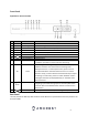
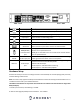
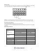
Front Panel Applicable for Amcrest AI DVRs # 1 2 3 4 5 6 7 8 9 Icon Alarm REC HDD NET ACT Power IR ESC Name Alarm Status Recording Status HDD Status Network Status Enter Power Status Power Button Infrared Sensor Escape FN Assist 🔺/🔻 Enter Up/Down/Enter 10 11 12 USB 2.0 port Function(s) When an alarm event occurs, this LED turns blue. When recording to the hard drive, this LED will turn blue. HDD error or the HDD is at capacity. Network error or disconnection has occurred.
Button Icon USB 2.0 port Network port Description USB 2.0 port. Connect a mouse, USB storage device, etc. 10M/100Mbps self-adaptive Ethernet port. HDMI HDMI Output VGA video output port GND High definition audio and video signal output port. VGA video output port. Outputs analog video signal. This connects to the monitor to view analog video.
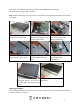
A hard drive - not included (unless you purchased a ‘kit’ that does have one included) Four hard drive fastening screws – included Note: Before installing the hard drive, make sure the DVR is powered off and completely disconnected from power. 1. Loosen the screws on the upper cover and side panel. 2. Attach four screws on the HDD (Do not fully tighten, only tighten about 3 times). 3. Place the HDD in accordance with the four holes on the bottom of the casing. 4.
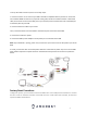
To set up the cable connections, there are 5 major steps: 1. Connect a monitor or TV screen to your DVR. The DVR is compatible with any monitor or screen that uses a VGA or HDMI connection. For purposes of this guide, we will use a VGA connection. Take a VGA cable, and connect one end to the VGA port on your monitor/screen and the other end to the VGA port on the back panel of your DVR. 2. Connect an Ethernet cable to your router.
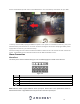
On the motherboard you will notice a small black button. This is the factory reset switch for your DVR: To factory reset the DVR, unplug the DVR from power. Once power is removed from the unit, press, and hold the factory reset switch for 4 - 5 seconds. Continue holding the reset switch and plug the DVR's power supply back into the unit, you will hear a beep. Continue holding the reset switch and allow the DVR to initialize for 20 - 30 seconds and then release the switch.
Alarm input port Connect the positive end (+) of the alarm input device to the alarm input port (ALARM IN 1~2) of the DVR. Connect the negative end (-) of the alarm input device to the ground end ( ) of the DVR. Figure 2-7 Note When connecting the ground port of the alarm device to the DVR, you can use any of the GND ports. When there is peripheral power supplying the alarm device, ensure it is grounded on the DVR.
Audio Ports Device-end to PC-end Device Connection Connect an RCA microphone to the “Audio In” port on the back of the device. If using an audio out device, such as an RCA speaker, plug the speaker into the “Audio Out” port on the back of the device. Most audio codecs will use ACC as a default audio codec. To adjust audio settings, log into your DVR and access the Encode menu for the specific device and click on “More Setting” (Camera > Encode > More Setting).
Move mouse Drag mouse Select current control or move control Select the motion detection zone Select the privacy mask zone Device Installation After turning the system on allow the device to boot. The default video wall will display along with a device initialization screen. Follow the on-screen prompts to complete initialization. 1. Set a Region, Language, and Video Standard 2.
3.
Create a new admin password for your device. The password for your device should be between 8 and 32 characters with a combination of letters, numbers, and symbols. Note: Please do not use special symbols like ‘“; : & Once you have entered a new password for your device, confirm the password in the next field. Lastly, you will be asked to enter a prompt question for your account. This is useful if you have forgotten your password and would like an easier means of recovering your password.
If you have assigned an unlock pattern, you will need to draw the pattern again to confirm. 5. Password Protection An Additional means of password protection and retrieval can be set up in this menu. If you would like to reset your password via email, toggle the Reserved Email toggle switch to the on position and enter a valid email address in the Reserved Email field. The email address will be retained in the system. If you do not wish to use an email address, you can enter security questions.
Once this section is complete, click on the OK button to save your information to the device. 6. Basic The next screen is the Basic settings screen. This screen allows you to set a language, video standard and other basic settings for the DVR. Once you are satisfied with the settings on this screen, click the Next button at the bottom of the screen. 7. Date & Time This menu allows you to set the date and time for the DVR.
Note: Make sure to toggle the NTP toggle switch to the off position if you do not want to sync your device to the NTP server. 8. Network In this screen you can configure basic network settings. Please note, it is highly recommended to have a static IP to ensure the device has a more stable connection with your network, as well as provide a more efficient means of accessing your device remotely. Toggle the DHCP toggle switch to the off position.
9. P2P This option will be enabled by default. It is highly recommended to keep this enabled if you want to use, the Amcrest View Pro mobile app or AmcrestView.com to view your cameras remotely using a P2P connection. Use the provided QR codes to download the mobile app and access the device’s serial number. Click Next to continue. 10. Audio/Video This screen allows you to adjust the video quality and encode settings on the main and sub streams of a connected camera.
After adjusting the video and audio settings, click Next to continue. 11. Snapshot This screen allows you to adjust the settings such as the image size, quality, as well as intervals in which the snapshot is retained. Once set, click Next to continue. 12. Basic The next screen that will appear will be labeled Basic. This is where you can configure your hard drive settings including, when to overwrite a full hard drive or customizing an auto-delete option.
13. Record The DVR is configured by default to record general (continuous recording), motion detection, and IVS record types on all channels 24/7, however, this section allows you to create a schedule for your recording types. 14. Snapshot The snapshot menu allows you to configure your snapshot settings for scheduled recordings. You can also use this screen to set up general, motion detection, IVS and other recording type schedules for snapshot events.
Video Wall After the device boots up, the system is in video wall mode. Please note the displayed window amount may vary. The following figure is for reference only. If you want to change the system date and time, you can refer to general settings (Main Menu>Setting>System->General). If you want to modify the channel name, please refer to the display settings (Main Menu->Camera->Channel Name). Please refer to the following sheet for detailed information.
Use the middle mouse button to control window split: You can scroll the middle mouse button to switch the window split amount. Preview Control Interface Move the mouse to the top center of the video of the current channel, and the system pops up the preview control interface. If your mouse stays in this area for more than 6 seconds and preforms no operation, the control bar automatically hides.
This is to back up the video on current channel to the USB device. The system cannot backup the video of multiple channels at the same time. Click the button and the system begins recording. Click it again and the system stops recording. You can find the recorded file on the USB device. 4) Manual Snapshot Click to take 1-5 snapshots. The snapshot files are saved on the USB device or HDD. You can go to the Search interface to view.
PTZ Right mouse click (press the “Fn” Button on the front. Please note you can only go to the PTZ control interface when you are in 1-window display mode. Please note the command name is grey if the device does not support this function. The PTZ operation is only valid in one-window mode. Here you can control the PTZ direction, speed, zoom, focus, iris, preset, tour, scan, pattern, aux function, light and wiper, rotation, etc. Speed is to control the PTZ movement speed. The value ranges from 1 to 8.
In the middle of the eight direction arrows, there is a 3D intelligent positioning key. Please make sure your protocol supports this function and you need to use the mouse to control it. Click this key and the system goes back to the single screen mode. Drag the mouse in the screen to adjust the section size. The dragged zone supports 4X to 16X speeds. It can use PTZ automatically. The smaller zone you dragged, the higher the speed.
Click to go to the following interface to set preset, tour, pattern, and scan. Preset Setup Click the Preset button and use the eight direction arrows to adjust camera to the proper position. Click the box next to Preset and then input the preset number. Click the Set button to save the current preset. Tour Setup Click the Tour tab. Input tour value and preset No. Click the Add preset button to add the current preset to the tour. Tips Repeat the above steps to add more presets to the tour.
Scan Setup Click the Scan button. Use the direction buttons to set the camera’s left limit and then click the Left button. Use the direction buttons to set the camera’s right limit and then click the Right button. Now the scan setup process is complete. Call PTZ Function Preset Input the Preset value and then click to call a preset. Click again to stop the call. Call Pattern Input the Pattern value and then click to call a pattern. Click again to stop the call.
Click to enable the camera to flip its image. The system supports preset, tour, pattern, scan, rotate, and light functions. Note: Preset, tour, and pattern all need the value to be the control parameters. You can define it as you require. You need to refer to your camera user’s manual for the Aux definition. In some cases, it can be used for special a process. Aux Click and the system goes to the following interface. The options here are defined by the protocol.
In the All Downloads menu, click on IP Config Software to begin the free download. Once the download has completed installing, locate the IP address associated with the device you would like to view in the browser. Enter this IP address into the Internet Explorer browser and press enter to load the web user interface. In the web user interface, enter the login credentials for your device. If this is the first time accessing the device, the username and password will both be admin. Click on Login.
Click Run to download the plugin. The browser will then show the live feed of your connected device in the web user interface. If the process above is not working, please contact Amcrest Support via one of the following options: Visit http://amcrest.
BACKUP: Search and backup files using a USB flash drive. DISPLAY: Configure resolution and display settings. AUDIO: Configure audio announcements and import audio files. Management CAMERA: Add, search, review or edit settings for each camera, including video settings (e.g. quality, bit rate, color, etc.). NETWORK: Review and edit TCP/IP, connection, DDNS, Email settings, etc. (e.g. P2P, UPnP, Multicast, etc.) STORAGE: Set recording schedules, as well as access the hard drive management interface, FTP, etc.
Below is a description of the Channel: In the Channel list, select the channel that you want to configure. Cable Type: In the Cable Type list, select the cable type that the camera uses. Period: In the Period list, select a time period for the image settings. The image settings will be only used during the selected period. Effective Time: Enable the effective function. In the Effective Time box, enter the start time and end time for the period you selected. Brightness: Adjusts the image brightness.
Color Mode: This dropdown menu allows the user to set color mode presets such as, bright, soft, vivid, etc. Color modes can also be customized using the Custom selections provided. Image Enhance: Adjusts the image definition. The bigger the value is, the clearer the image will become, but there will be more noises. NR: Reduces the noises from image. The bigger the value is, the better the image will become. Image EQ: Adjust the image equalization.
Smart Codec is a function in most Amcrest cameras which aim to reduce bandwidth consumption without losing visible image quality by intelligently increasing compression where it will not make a visible difference in the scene. AI Coding takes video compression to a new level of content awareness. It puts emphasis on humans and vehicles while encoding, significantly improving the stream quality compared to H.265.
Below is a list of snapshot settings that can be modified on this screen: Channel: This dropdown box allows the user to select a channel from the dropdown list to modify. Type: There are 2 snapshot modes, Scheduled and Event. Scheduled types will allow the feature to retain snapshots continuously, event mode will allow a snapshot to be retained when an event occurs. Size: This dropdown box allows the user to select an image size. This may be unavailable (grayed out) on certain models.
Record: This checkbox allows the user to set a privacy mask on the live view screen and while recording. Channel Title: This button allows the user to select whether the system displays channel number on playback video. Clicking the set button allows the user to drag the title to the corresponding position on the screen. Time Title: This button allows the user to select whether the system displays time on playback video.
Below is a description of the fields in this menu: Snapshot Path – The designated storage path for all downloaded snapshots. Record Path – The designated storage path for all downloaded recordings. To set a storage path, click on the Browse button and select a storage path or folder in which snapshots or recordings will be downloaded. To revert to default settings, click the Default button. To confirm settings, click the OK button. PTZ This screen is used to configure Pan/Tilt/Zoom (PTZ) functionality.
For more information on the settings listed in this menu, please refer to the information provided below. Channel: In the Channel list, select the channel that you want to connect the PTZ camera to. Type: Local: Connect through RS485 port or coaxial cable. Remote: Connect through network by adding IP address of PTZ camera to the DVR. Control Mode: In the Control Mode list, select Serial. For series product, please select the control signal is sent to the PTZ through the coaxial cable.
Press the Refresh button to refresh the interface. To confirm settings, click the OK button. Connecting an IP Camera To connect an IP camera to your DVR, please follow the steps provided below: Note: The number of IP cameras added to the DVR is dependent on how many channels your specific model can handle. An added IP camera will replace one active channel in the DVR. 1. Click on the Camera option located in the Management section of the Main Menu. 2. Click on Channel Type and select the IP Camera option.
Network This menu controls all network related functions for the DVR and governs how the DVR interacts with a connected network. TCP/IP TCP/IP stands for Transmission Control Protocol/Internet Protocol and it is the language/protocol that allows communication between internet connected devices, whether on a local network, or a on the Internet at large. This screen allows for TCP/IP settings to be modified for the DVR to establish connection to the network.
Below is an explanation of the fields on the TCP/IP settings screen: NIC Name: The name of the NIC card in the device. IP Address: This field allows the user to enter a custom IP address. Network Mode: The current NIC mode detected by the system. The system only supports a single NIC. NIC Member: The NIC number that is being detected by the system. Modify: Click the pencil icon to edit TCP/IP information. NIC Name: The current name of the NIC card. Network Mode: The current NIC mode detected by the system.
current value and reboot or can click the Cancel button to terminate the current modification. Before the modification, you can check the MTU of the gateway; the MTU of the DVR should be the same or lower than the MTU of the gateway. This way, packets can be reduced, and the network transmission efficiency be enhanced. The following MTU values are for reference only. 1500: Ethernet information packet maximum value and it is also the default value. It is the typical setup when there is no PPPoE or VPN.
Below is an explanation of the fields on the Connection screen: Maximum Connection: This field represents the maximum number of users that can be connected to the DVR at the same time. The maximum number of users the DVR can support at one time is 128. TCP Port: This field designates the Transmission Control Protocol (TCP) port number. The default value is 37777. UDP Port: This field designates the User Datagram Protocol (UDP) port number. The default value is 37778.
The HTTPS cert will need to be created, log into the device and access the HTTPS menu. Click on the Create Server Certificate button. Enter the necessary credentials for your HTTPS certificate and click Create. The browser will reset again and will automatically load the login interface. You will notice the IP address has changed to HTTP and the security report will show a lock symbol indicating the cert has been created properly.
DDNS DDNS stands for Dynamic Domain Name Server. This technology is used to automatically update name servers in real time to help the DVR maintain a persistent address despite changes in location or configuration. What this means is that even when the DVR is restarted, moved, or reconfigured, it can keep the same IP address, thus allowing remote users uninterrupted access to the DVR, rather than having to request a new IP address to use for remote access anytime a change is made.
MAC address: This field shows the DVR’s MAC address, which is unique to this device. This number is read-only and is used to access a local area network (LAN). Internet Status: The DDNS connection status. For more information on how to setup DDNS service for your device, please visit amcrest.com/support Press the Refresh button to refresh the interface. To confirm settings, click the OK button.
The fifth column shows the External Port used by that service. To edit this, double click on the service line item. Press the Refresh button to refresh the interface. To confirm settings, click the OK button. Email This screen allows for the configuring of email settings to permit the DVR to send emails when the connected cameras or alarms are triggered.
Sender: This field allows the user to enter the sender email address. This email address will be the one that sends out all emails pertaining to the alerts and alarm emails sent by the DVR. Encrypt Type: This dropdown box allows the user to select an encryption type. There are two types of email encryption that are available. SSL: Secure Socket Layer TLS: Transport Layer Security Subject: This field allows the user to define the subject line of the email that is sent to the receivers.
ID: The ID number that is applicable to the proxy address. Click the Refresh button to refresh the interface. To confirm settings, click the OK button. P2P The P2P screen allows users to access a QR code to connect their smartphone or tablet to the DVR. The device uses an app called Amcrest View Pro, and it is available on both iOS and Android. Below is a screenshot of the P2P settings screen: Enable: This checkbox allows the user to enable the P2P feature for the DVR.
Before the DVR can be accessed through the app using the easy plug-and-play method (P2P Setup), P2P must be enabled on the DVR. Enabling P2P P2P should be enabled on your device by default, however, to check if P2P is enabled, please follow the information provided below. Log into your DVR and access the Main Menu. In the Management section, click on Network then click on P2P. Ensure the Enable toggle switch is enabled and the P2P status says “Online”. This indicates the P2P option is enabled.
3. Tap “P2P Connection”. Note: IP/Domain/DDNS can be used to establish a DDNS connection. For more information on how to setup a DDNS connection, visit amcrest.com/support 5. Create a name for the device and enter a username and password. The default username and password will be admin. Tap “Start Live View”. 4. Scan the QR code. The QR code can be found on the serial tag along with a scannable barcode. 6. Update the default password for the device and tap “Start Live View” to view the device.
Storage This menu allows the user to update, modify, and manage device storage settings within the DVR. For more details on this menu please refer to the sections below. Basic This menu allows the user to set hard drive (HDD) overwrite permissions for the system. Below is a screen shot of this menu. Below is a description of the features listed in this menu: Disk Full – Allows the user to set a overwrite mode for their recordings.
Below is an explanation of the fields on the Record settings screen: Channel: This dropdown box allows the user to pick which channel they would like to change video recording settings for. Prerecord: This field allows the user to capture extra video that occurs before an event. Up to 30 seconds of video prior to a recording event can be captured to provide context to a recording.
Click the text next to each period to edit the time you wish to set for that specific period. Next, choose which record type you would like to set for each period. You will also need to select the days you wish to apply these settings. To select all days, select all options to apply the settings to all days of the week. Click Save to save this schedule to the system. To revert to default settings, click the Default button. To copy settings to another channel, click Copy to.
Below is an explanation of the fields on the Snapshot settings screen: Channel: This dropdown box allows the user to pick which channel they would like to change video recording settings for All: Link all days of the week to a selected recording type schedule. Record Types: There are 5 types of recordings: General: General recording means that the DVR captures all snapshots for the specified time period. Regular recording is represented by green.
HDD Manager This screen is used to help the user monitor the DVR’s hard drives. Using this screen, the user can see the current HDD type, status, and capacity. The user can also use this screen to format hard drives and change hard drive properties. Below is a screenshot of the HDD Manager settings screen: Below is an explanation of the fields on the HDD Manager settings screen: No.: Displays how many HDDs the system is supported.
Below is an explanation of all the fields on the Record settings page: Main Stream: The main stream is the stream through which the channels transmit data by default. There are 3 settings that can be used for the mainstream. Auto: Channels will record as they have been scheduled, and not in any other capacity. Manual: Channels will support all recording type. This includes scheduled recording. Off: Channels will not record in any capacity. This includes scheduled and manual recording.
To group a hard drive, use the Disk Group dropdown menu to choose a group in which the hard drive will apply and click OK. After configuring the hard drive group, click the Main Stream, Sub Stream and Snapshot tabs respectively, to configure the groups to main stream, sub stream and snapshot information of different channels to different HDD groups. Be sure to click OK on each tab to save its respective configuration.
Below is an explanation of the fields on the FTP settings screen: Enable: This checkbox allows the user to enable the FTP feature for the DVR. FTP: Enables FTP. Server Address: This field allows the user to enter the FTP server IP address and port. Port: The port number of the FTP server. The default port number is 21. Username: This field allows the user to enter the FTP username. Password: This field allows the user to enter the FTP server password.
Channel: This settings button allows the user to select a channel in which the FTP will apply. For more information how to setup FTP settings, please visit amcrest.com/support To reset the interface back to default, click the Default button. To test the current settings, click Test. To refresh the interface, click the Refresh button. To confirm settings, click the OK button. System General This screen displays general settings for the DVR.
Date and Time This screen displays date and time settings for the DVR. Below is a screenshot of the Date & Time settings screen: Below is an explanation of the fields on the Date & Time settings screen: System Time: This field allows the user to set the system time and time zone. Click Save to save the system time as it is shown in the display. System Zone: This dropdown box allows the user to specify a time zone for the DVR to use.
Time Format: This dropdown box allows the user to specify a time format for the DVR to use. There are two options. 24 Hour 12 Hour DST: This option allows the user to activate DST for the system. DST Type: This field allows the user to pick whether DST starts on a specific day of the week, or on a specified. Start Time: This field allows the user to enter a start date and time for DST to begin. End Time: This field allows the user to enter an end date and time for DST to end on.
Stop: The holiday is inactive, and the DVR will continue normal operation for that holiday period. Name: This column is where the name of the holiday is displayed. Date: This column shows the date that the holiday occurs on. Duration: This column shows the range in which the holiday occurs. Operation: This column allows the user to edit or delete the holiday. Edit ( ): This column has a button that allows for the editing of the holiday.
Below is a description of the fields in the security settings screen: Type: This dropdown menu allows the user to select which type of firewall will be included. There are 3 types of firewall settings. Network Access: Prevents a set IP address from network access. Ping Prohibited: Prevents the device from pinging a set IP address. Anti-Half Connection: Prevents the device from partial connection to a set IP address. Enable: This option allows the user to enable the firewall feature.
The maximum number of users is 64, and the maximum number of users that can be in one group is 20. There are two levels for user management: administrator and user. Administrator has more rights than a normal user and can modify key DVR settings. Each user can belong to only one group, and user rights cannot exceed group rights. User This screen is used to configure User Account settings.
Note: It is recommended to give the general user fewer rights than an administrative one. When a new user is created, a MAC address can be entered for the user. This can limit the user's ability to logon from another device. If left blank, the user can logon from any MAC address. There is a total of 98 rights that can be assigned to a user. Group This screen is used to configure Group account settings.
Below is an explanation of the fields on the Group settings screen: No.: This number indicates how many groups are in the system. Each line item has a number to signify its place in the list. Group Name: This column indicates an account's username. Remarks: This column indicates any notes about the user group. Modify: This column has a button that allows for the account's properties to be edited. Delete: This column has a button that allows for the account's properties to be deleted.
To confirm settings, click the Save button. Click the Refresh button to refresh the interface. Live The live view interface provides a real-time viewing of a connected device. Below is a description of the options in this menu: Channel List: The amount of HDCVI channels currently available on the system. Start Talk: Enables two-way audio if an external and microphone and speaker are connected. Instant Record: Instantly starts recording video (a hard drive must be installed).
PTZ Menu: Used to configure PTZ presets. For more information on how to setup a PTZ preset, if applicable, please visit: amcrest.com/support Search The Search menu allows the user to view recorded data retained in the system. This includes recording types such as regular, motion detection, (MD), Alarm, and IVS. The system will need a hard drive installed to view recorded events. Please refer to the following sheet for more information.
CAM Name – This section provides names of connected cameras on the device. If data is applied to any of these channels, a timeline of the events will be displayed in the time bar interface. Please note, the user can switch between mainstream and sub stream recording by clicking on the “M” (mainstream) and “S” sub stream icons. Duration and Modes: This section allows the user to view 24-hour, 2 hr., 1hr, or 30min recording intervals.
Human/Vehicle Filter: Filter between human and vehicle events. Full Screen: Click this button to view the event in full screen mode. Clip: Used to clip an event by entering a start and end time for the clip. Save: Used to save and download a created clip. Time Bar Digital Zoom Provides a timeline of all recording types for a selected channel. Different recording will be displayed in different colors on the timeline.
To exit, click on the Smart Search option and select Yes to exit. Accurate Playback by Time Select records from one day, click the list, and you can go to the file list interface. You can input a time at the top right corner to search records by time. For example, input time 11:00.00 and then click the Search button , and you can view all the record files after 11:00.00 (The records include the current time.). See image on the right side of the Figure 4-68 Double click a file name to playback.
Playback Mark During 1-window playback mode, click the mark file list button and you can go to mark file list interface. Double click one-mark file, and you can begin playback from the mark time. Play before mark time Here you can set to begin playback from the previous N seconds of the mark time. Note: Usually, the system can playback the previous N seconds of the record if there is a recording. Otherwise, the system playbacks from the previous X seconds when there is a recording.
Alarm Info This feature allows the user to search for specific types of alarm information related to the system. These specific types of alarms include, Motion Detection, Video Loss, Tampering, Abnormalities, Local Alarms, Intel, etc. You can also select All to view all log and alarm information. Here is a screenshot of the Alarm Info tab: To use this feature, access the alarm info interface and select the type of alarm you are search for from the dropdown menu.
Below is a description of the fields on the Motion Detection settings page: Channel: The channel dropdown menu is used to select which channel you would like to use to set your motion detection. Region: The setup button takes the user to the motion detection region setup screen for that specific channel. On the next page is a screenshot of the motion detection region screen.
When the setup button is clicked, the current channel’s interface comes into a full screen view. The user can then set up to 4 regions, each with their own region name, sensitivity (1-100), and threshold (1-100). Each region has a specific color, and the region selector tool is displayed when the mouse is moved to the top of the screen. Sensitivity is the amount of change required to increase the motion detected by a percentage. The lower the sensitivity, the more movement is required to trigger an alarm.
Click and drag on the yellow bars to specify time zones for motion detection. To edit multiple days at once, either click the checkboxes next to the names, or click the checkbox next to All to edit all the days at once. Once the checkbox is clicked, press save to save and apply your detection settings. Click Cancel to undo any changes and return to the motion detection settings screen. Click Default to use the default settings. The system allows for the configuration of up to 6 different time periods.
Below is a description of the fields on the Video Loss settings page: Channel: The channel dropdown menu is used to select which channel you would like to use to set your motion detection. Enable: This checkbox allows the user to enable the detection function for a specific channel. To select a channel, click on the drop-down menu provided on the right. Schedule: This setup button takes the user to the detection period settings screen. Below is a screenshot of the motion detection period settings screen.
Click and drag on the yellow bars to specify time zones for detection. To edit multiple days at once, either click the checkboxes next to the names, or click the checkbox next to All to edit all the days at once. Once the checkbox is clicked, press save to save and apply your detection settings. Click Cancel to undo any changes and return to the motion detection settings screen. Click Default to use the default settings. The system allows for the configuration of up to 6 different time periods.
Below is a description of the fields on the Tampering settings page: Channel: The channel dropdown menu is used to select which channel you would like to use to set your motion detection. Enable: This checkbox allows the user to enable the detection function for a specific channel. To select a channel, click on the drop-down menu provided on the right. Schedule: This setup button takes the user to the detection period settings screen. Below is a screenshot of the motion detection period settings screen.
Click and drag on the yellow bars to specify time zones for detection. To edit multiple days at once, either click the checkboxes next to the names, or click the checkbox next to All to edit all the days at once. Once the checkbox is clicked, press save to save and apply your detection settings. Click Cancel to undo any changes and return to the motion detection settings screen. Click Default to use the default settings. The system allows for the configuration of up to 6 different time periods.
Disk This screen allows the user to specify actions that occur when there is an abnormality with the DVR’s hard disk drive (HDD). Below is a screenshot of the HDD abnormality settings screen: Below is an explanation of the fields on the HDD abnormality settings screen: Event Type: This field allows the user to specify which HDD abnormality event type they would like to configure settings for. No Disk: No hard drive is detected. HDD Error: The hard drive has an error.
Below is an explanation of the fields on the Network abnormality settings screen: Event Type: This field allows the user to specify which Network abnormality event type they would like to configure settings for. Offline: The network connection has been disconnected. IP Conflict: There is a device on the network with the same IP address. MAC Conflict: There is a device on the network with the same MAC address. Enable: This option allows the user to enable the features below for the specified event type.
AI The AI menu allows the user to manage and view artificial intelligence and face recognition information and settings. AI features available on the device can be controlled either by the device or via a connected AI camera depending on its features. Face Detection Face Detection is typically used in conjunction with an AI DVR, however, can be used independently to detect faces. Please note, face detection cannot be used simultaneously with features such as IVS, etc.
Tour: Used to setup a tour for multiple channels. Please note, this is only applicable for PTZ controlled devices. PTZ Linkage: Allows the user to activate pan, tilt, and zoom options. Please note, this is only applicable to PTZ controlled devices. Alarm Tone: Plays an audio file set by the user once an alert is triggered. More: Access additional settings such as, buzzer, alarm upload, log, send email.
2. When triggered, the face detection event will be retained in the face detection smart search menu or snapshots of the event can be emailed to you. To enable Email snapshots, click on the More button and enable the Send Email checkbox and click OK. Face Recognition Face recognition is used in conjunction with face detection to locate and determine facial similarities detected by the system.
Use the channel dropdown to select a channel. Please note, the channel selected must reflect the same channel enabled in the smart plan menu. Enable: This option is used to enable face recognition. Schedule: Allows the user to set a schedule in which face detection will be triggered. General Alarm: General alarms are based off facial images imported from a face library. Stranger Alarm: This interface is used to trigger an event when a face is not recognized.
2. Click on the Face Database Config option located in the Database menu and click on Add to begin registering images to a face library. A face library must be registered for this feature to function properly. Enter a name for your face library and click OK. The library will now be saved to the database. Click on the Details section to begin adding images into the to the face library. If you have a single image to add click Register ID, if you have multiple images to add click on Batch register.
Please note IVS rules cannot be enabled if other AI rules are enabled on the device. The DVR currently has 2 built-in IVS features available (Tripwire and Intrusion). Below is a screenshot of the IVS menu: Below is a description of the features in this menu: Channel: Use this dropdown menu to select which channel will apply to the AI feature. No: Provides the order in which the IVS rules will be displayed in the menu. Name: Allows the user to customize a name for their rule.
Tripwire: Allows the device to trigger an event if an object, such as a human or vehicle, crosses a set tripwire line. Intrusion: Allows the device to trigger an event if an object, such as a human or vehicle, appears or crosses a set intrusion area. Setting an IVS Rule Use your mouse to draw an area or line on the interface. Click on the interface and use your mouse to draw an area or line, click your mouse on the interface when done, then right click to set the area or line to the system.
vehicle is detected by the system. Both object filtering options can be used simultaneously if needed. To reset to default settings, click the Default button. To refresh the page, click the Refresh button. To save the settings, click the OK button. Note: All IVS events can be viewed in the Playback interface or in the “Smart Search” option located in the Smart Search menu.
Effective Object: The object filter checkboxes allow the camera to be triggered only when a specific object, such as a human or car, is detected by the camera. Both effective object checkboxes can be activated at the same time. Human: This checkbox allows the camera to be triggered only when a human figure is detected. Motor Vehicle: This checkbox allows the camera to be triggered only when a vehicle has been detected.
any attributes of the event such as Gender, Age, Expressions, etc. that you would like to view in the Smart Search interface and click Search. A display of all face detection data will be displayed along with facial attributes. Click on the event you would like to view, and a clip of the event will be displayed in the built-in player. Click on the play icon to view the event.
Viewing Face Recognition Events All face recognition data retained by the system can be accessed via the Face Recognition option located in the Smart Search menu. A search by attributes or a search by image can be performed. Searching by attributes will load all face recognition data found in the system whereas searching by an image will filter and display only the faces chosen by the user. To search by attributes, enter a start and end time of the event in the interface and then click Search.
If searchable images are already uploaded into a face library click on Face Library and select an image from the interface, then click Save to begin a search. If you would like to add images locally click Local Upload and follow the on-screen prompts to upload images. A USB flash drive with applicable images (in jpeg format) can be used to upload images to the DVR. Once an image has been loaded, enter a start and end time of the event, and click Smart Search.
A layout of all IVS events will be displayed. To view the event, select the event from the interface and click the play button. To download the IVS event, select the event from the interface and click on Backup. Choose a file path for the recording and click Backup. The event will be downloaded to the set file path. Viewing SMD Events Any SMD data retained on the system can be viewed using the SMD Smart Search interface or via the playback menu if an SMD schedule is set in the system.
To view the SMD event, click on the Play icon to automatically play the SMD event. To download the SMD event, select the event from the interface and click on Backup. Choose a file path for the recording and click Backup. The event will be downloaded to the set file path.
Maintain The Maintain menu allows the user to view system information, update, import and export configuration settings, etc. Log This menu allows the user to view log information retained in the system. The system will automatically retain logs of events which occur during normal operation. Below is a screenshot of this menu: Below is a description of the features in this menu: Type: Use this dropdown menu to select a log type.
Disk The HDD tab provides information about a connected hard drive in the system. Below is a description of the fields listed in this menu: Number: The number represented in the system for the hard drive. Device Name: The name assigned by the system for the connected hard drive. Physical Position: Displays the location of the connected hard drive on the system. Type: The read and write type assigned to the hard drive. Free Space/Total Space: The total space used on the hard drive. S.M.A.R.T: S.M.A.R.T.
Channel Info The Channel Info tab allows the user to view any errors associated with a connected hard drive. The interface can detect the name, amount of space left, the manufacturer, serial number, and current health status of the drive. Below is a screenshot of the interface: Below is a description of the fields listed in this menu: Channel: The channel number that is being monitored. Cam Standard: The status and type of camera being monitored.
No: The number assigned to the user in the system. Username: The username of the connected user. Group Name: The group name associated with the connected user. IP address: The IP address used by the connected user to access the system. User Login Time: The date & time which the user logged into the system. Refresh: This button is used to refresh the interface.
Below is an explanation of the fields on the Import/Export settings screen: Export: Used to export device configuration files to the device. Browse: Click this button to select the device configuration file from Import: Click this button after the config file has been imported into the interface to import the settings. Default This screen is used to revert the DVR back to its original default or factory default settings.
To begin upgrading the firmware, click on Download the latest Firmware and locate the firmware file for your specific device. Download the firmware to a USB flash drive or to the computer if using a web user interface. Click on Browse to locate and import the firmware (.bin) file into the interface. Click System Upgrade and allow the device to complete the upgrade process. Note: The device will reset after the firmware upgrade is complete.
start and end time of the event and the file format from the Type dropdown menu. Click Search to import all recorded data. Note: A view the event before it is downloaded, click on the Play icon. Select the event from the interface and click Back Up. The chosen files will be backed up to the file path previously chosen. Note: Click on the Watermark option to verify the watermark information assigned to the downloaded file.
For more information on the settings provided in this menu, refer to the table provided below. Parameter Main Screen Time Title Channel Title Original Ratio AI Rule SMD Preview Resolution Transparency Resolution Description The main display outputs. The device should be VGA+HDMI by default. This checkbox enables the time overlay on the display. This checkbox enables the channel overlay on the display. This checkbox sets the display into its original aspect ratio.
Below is an explanation of the fields on the Tour screen: Enable: This checkbox allows the user to enable the tour functionality. Interval: Enter the amount of time that you want each channel group displays on the screen. The value ranges from 5 seconds to 120 seconds, and the default value is 5 seconds. Motion Tour Select the View 1 or View 8 for Motion tour. Alarm Tour: Select the View 1 or View 8 for Alarm tours (system alarm events).
When you have finished selecting the appropriate group order, click OK to complete the process. If you do not wish to proceed with the group function, click Back to exit the add group interface. Modifying a Channel Group To modify an established channel group, double-click on a channel group to access the Modify Channel Group interface. In the modify channel group interface, select the group order for your selected group and click OK to complete the process.
Below is a description of the zero-channel menu: Enable: This checkbox is used to enable the zero-channel function. Compression: Allows the user to select a video compression standard. Resolution: Allows the user to select a video resolution. The default resolution will be 704x480(D1) Frame Rate (FPS): Allows the user to select a value between 1 and 25 for PAL standard, and between 1 and 30 for NTSC standard.
For more information on the features listed in this menu, refer to the table provided below. Parameter Description Period In the Period box, enter the time. Select the check box to enable the settings. You can configure up to six periods. In the File Name list, select the audio file that you want to play for this configured period. In the Interval box, enter the time in minutes for how often you want to repeat the playing. Configure how many times you want to repeat the playing in the defined period.
• • • • • The power button is damaged or malfunctioning. Video output signal is not stable. The insides of the DVR have accumulated too much dust. The temperature is either too hot or too cold. The hardware is malfunctioning. 3. The system does not detect a hard drive. Below are a few possible reasons why this may be occurring: • • • The hard drive is broken. The hard drive cable is damaged. The hard drive cable connection is loose. The DVR's main motherboard SATA port is broken. 4.
• • • • • The video quality setting is too low. The DVR software has a read error. Restart the DVR to solve this problem. The hard drive cable is damaged. The hard drive is malfunctioning. The DVR's hardware is malfunctioning. 8. There is no audio during real-time monitoring. Below are a few possible reasons why this may be occurring: • • • • The microphone being used is not sufficiently powered. The speakers being used are not sufficiently powered. The audio cable is damaged.
• • • • • • • • Motion detection sensitivity is too low. 13. Web Access is not working. Below are a few possible reasons why this may be occurring: Windows version is pre -Windows 2000 service pack 4. Use a more recent version of Windows. ActiveX controls have been disabled. The PC is not using DirectX 8.1 or higher. Upgrade to a more recent version of DirectX. The DVR is having network connection errors. Web access may be setup incorrectly. The username or password may be incorrect.
18. Alarms are not working. • • • • Below are a few possible reasons why this may be occurring: The alarm is not setup correctly. The alarm cable is not connected correctly. The alarm input signal is not correctly configured. There are two loops connected to one alarm DVR. 19. The camera is not recording enough video. • • Below are a few possible reasons why this may be occurring: The hard drive's capacity is not enough. The hard drive is damaged. 20. Downloaded files cannot be played back.
(b) For a Class B digital DVR or peripheral, the instructions furnished the user shall include the following or similar statement, placed in a prominent location in the text of the manual: NOTE: This equipment has been tested and found to comply with the limits for a Class B digital DVR, pursuant to Part 15 of the FCC Rules. These limits are designed to provide reasonable protection against harmful interference in a residential installation.
Circuit Board ○ ○ ○ ○ ○ ○ Fastener ○ ○ ○ ○ ○ ○ Wire and Cable/AC Adapter ○ ○ ○ ○ ○ ○ Packing Material ○ ○ ○ ○ ○ ○ Accessories ○ ○ ○ ○ ○ ○ Note O: Indicates that the concentration of the hazardous substance in all homogeneous materials in the parts is below the relevant threshold of the SJ/T11363-2006 standard.