Amcrest IP4M-1046EW / IP4M-1046EB 4MP POE 4MP AI Bullet Camera User Manual Version 1.0.
Contents Welcome ................................................................................................................................................. 3 Important Security Warning .................................................................................................................... 3 Important Safeguards and Warnings ....................................................................................................... 3 Features and Specifications .................................
Welcome Thank you for purchasing an Amcrest camera! This user manual is designed to be a reference tool for the installation and operation of your AI camera. Here you can find information about the camera’s features, functions, and information to aid in troubleshooting. Many of the setup and installation sections below have corresponding videos on YouTube To access the setup videos, please go to http://amcrest.
5.Environment The camera should be kept in a cool, dry place away from direct sunlight, flammable materials, explosive substances, etc. This product should be transported, stored, and used only in the specified environments as stated above. Do not aim the camera at a strong light source, as it may cause overexposure of the picture, and may affect the longevity of the camera’s sensors. Ensure that the camera is in a well-ventilated area to prevent overheating. 6.
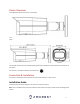
Device Overview The image below shows the structure of the camera: The images below show the dimensions for the camera. The measurements are in millimeters (mm): To access the reset button and to adjust the camera angle, use the included Torx/Hex wrench. The reset button and microSD card slot can be accessed by removing the 2 screws located on the security hatch on the bottom of the camera.
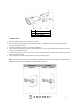
1. 2. 3. 4. Network Camera Mounting Screws Wall Anchors Install Template Installation Guide 1. 2. 3. 4. 5. 6. Stick the installation sticker on the installation surface. Drill through the holes provided on the installation sticker. A 1” paddle bit can also be used if installing wires through an installation surface. Insert the included wall anchors into the newly drilled holes. Align the bottom bracket of the camera to the installation holes.
MicroSD Card Installation Guide To Install a microSD card into your camera, please refer to the step by step guide below: 1. 2. 3. Remove the security hatch cover located on the bottom of the camera with the included torx wrench. Locate the provided microSD card slot and insert the microSD card into the slot, (Gold pins down). Push the microSD card into the slot and release, the microSD card will then be locked into place and ready for use.
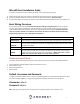
How to Setup the Camera To make your experience with your Amcrest camera easy and simple, we've provided multiple ways to set up, view, and operate your camera depending on your needs. Please follow the instructions on this page to set up your camera in the way that works best for you. Setting up Your Camera for the First Time If you are setting up your camera for the first time, or you are setting up your camera for mobile viewing.
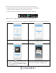
• • Make sure your camera and mobile device are on the same network during setup. To ensure the camera connects to the cloud, a reboot of your camera is recommended. To add your camera onto the Amcrest Cloud app, follow these steps: 1. Download and open the Amcrest Cloud app from the App Store or Play Store. Note: Connect your mobile device to the same network that your camera is on. 2. Register for an Amcrest Cloud account. To register click on Sign Up and fill out the form to complete registration. 3.
7. Set a new password for your camera. The password must be between 8 to 32 characters long and contain only letters and numbers. When you have finished setting the password for your camera, enter the password again in the Confirm Camera Password section. Tap Next to continue. 8. Confirm and adjust any needed settings for your camera. When all settings have been confirmed, tap Finish. For more information about the Amcrest Cloud app and its features, visit amcrest.
2. Open the app and tap on the + symbol in the middle of the screen to begin adding your PoE device. 3. Tap on Add Device to add a new device to your app. 4. Tap on PoE Camera 5. Next, select a connection type. Since we will be setting up a basic P2P connection with the device, tap on "P2P Connection" to continue.
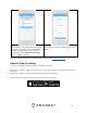
6. Scan the QR code on the back/side/bottom of the camera or manually enter the camera’s serial number into the Enter camera S/N (serial number) field. Press Next to continue. 7. Give the camera a name (e.g. Garage, Kitchen, Living Room, etc.) and provide the username and password for your camera. The default username and will be admin. Tap Start Live View to continue. Note: You can tap on the icon to verify the password. Note: Android users, tap on Scan QR Code to access the QR code reader. 8.
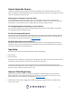
Desktop Access Setup The AI features associated with your camera are only accessible and customizable using the built-in web user interface via a web browser. This camera features the latest in JS technology which allows you to access your camera via a wide variety of web browsers including, Google Chrome, Firefox, Safari and other mainstream web browser via your PC or Mac computer.
If this is the first-time logging into your device, you will be prompted to modify the password for your device. To modify the password, enter the new password you would like to use in the New Password field and confirm. The password used should be between 8 and 32 characters long with a combination of letters and numbers. Click OK when and allow the stream to load.
Operation and Interface This section will show you the basic operation and interfaces of the web user interface for your camera. Live By default, the interface opens on the Live tab. The live view tab allows the user to see a live video feed from the camera. The live view tab has five main sections: Section 1: These options allow the user quick access to the live view screen, playback, as well as to the Amcrest Cloud.
Section 6: This bar allows the user to change video settings for the live playback screen. See the below table for an explanation of the video settings: Button Function Name Function Description Image Adjustment This button opens the image adjustment toolbar, which allows the user to adjust brightness, contrast, saturation, and hue for the live feed’s picture.
This is the interface for the playback menu. There are 7 main sections: Section 1: Allows the user to filter between video (.mp4) or snapshots (.jpg) Section 2: Allows the user to playback events based on calendar dates. If events are detected via the microSD card the days will be highlighted indicating recordings are available for that day. Section 3: These options allow the user to access/download recordings to their computer.
There are 3 main sections to note in the Setup tab: 1. 2. 3. Menu Bar: The menu bar is composed of menu sections, which when clicked display any menu items that fall under their category. Menu Items: These menu items each open a different menu that allows the user to change specific settings for the camera. Menu Tab: These tabs open menu options for certain menu items. Camera This menu section allows the user to change different camera settings for video and to manage image profiles.
• • • • • value is too low. If this value is too high, the dark section may lack brightness while the bright section may over expose. The recommended value ranges from 40 to 60. Saturation: This slider is used to adjust playback and recorded video window saturation. The value ranges from 0 to 100. The default value is 50. The larger the number, the stronger the color is. This value has no effect on the general brightness of the whole video. The video color may become too strong if the value is too high.
▪ ▪ ▪ • • • gainFirst - This setting will maximize the gain for the ideal exposure. Low Noise Basically turns up the ISO to the best setting without sacrificing exposure timing. Shutter Priority - This setting will maximize the fastest shutter speed and will sacrifice the gain in return. Manual - This setting lets you select your shutter speed and have the gain adjust automatically. Selecting customized range will let you both the shutter speed an adjust the gain manually.
Selecting customized opens a menu that allows the user to set specific red or blue values. Regional custom allows the user to select an area (region) on the live view screen in which white balance will be most applicable. Below is a screenshot of this menu: To reset to default settings, click the Reset Defaults button. To refresh the screen, click on Refresh. To save the settings, click the Save button.
• • • • • • • Profile: This dropdown box allows the user to select which profile to modify. The 3 options are Day, Night, and Normal. Mode: This dropdown box allows the user to select different Day & Night balance modes. The 3 options are Auto, Color, and B&W. Auto - Uses D&N Sensitivity setting to change between color mode and infrared and black and white mode. Color - Preset which allows the camera to compensate color in day or night profiles.
Defog This menu allows the user to set defog settings which can be useful in foggy or hazy weather. Below is a screenshot of the Defog menu. Profile: This dropdown box allows the user to select which profile to modify. The 3 options are Day, Night, and Normal. Mode: Allows the user to adjust defog settings. OFF: Allows the user to turn off defog mode, Manual: Allows the user to manually control defog settings, Auto: Allows the user to let the camera automatically detect defog settings.
Profile Management: This set of radio buttons allow the user to set what basis the profile management settings run on. There are 4 options: General, Full Time, Schedule, and Day/Night. General means that the system can automatically alternate between night and day based on the profiles for each. Full Time means that the system sticks to one profile the entire time it is running. Schedule allows the user to dictate which times of the day are designated for the day profile and the night profile.
• • Watermark Settings: This function allows the user to verify if the video has been tampered with. Watermark Character: This field allows the user to set the watermark’s text. The default string is Digital CCTV. The maximum length is 85 characters. This string can only include numbers, characters, and underscores. Sub Stream is a lower quality stream that allows the feed to take up less resources and bandwidth when streaming. The Mainstream and the Sub Stream have the same fields.
The menu on the left allows the user to select which overlay to modify. Privacy Masking, Channel Title, Time, and Text Overlay can all be modified in this menu. For Privacy Masking, the radio button enables or disables the feature. To set a privacy mask, click one of the boxes in the live view window, and position or resize it as needed. To remove a box, click on it, then click the delete button. To remove all privacy filter boxes, click the remove all button.
• • • • • The Live Snapshot field allows the user to select where to save live snapshots to. Click the Browse button to select a different destination folder. The Live Record field allows the user to select where to save live recordings to. Click the Browse button to select a different destination folder. The Playback Snapshot field allows the user to select where to save playback snapshots to. Click the Browse button to select a different destination folder.
Below is an explanation for each of the fields on the Audio menu: • • • • • • Enable: This checkbox allows the user to enable audio recording. Encode Mode: This dropdown box allows the user to select what audio format the audio should be recorded in. Sampling Frequency: This dropdown box allows the user to select a sampling frequency for the audio. The options are 8k and 16k. 16k audio sampling allows for higher sound quality.
Below is an explanation of the fields on the TCP/IP settings tab: • • • • • • • • • • • Host Name: This text field allows the user to change the host device name for the camera. This field supports a maximum of 15 characters. Ethernet Card: This dropdown box allows the user to select which internet access device to use. If the device is connected to a wired connection and a wireless one at the same time, then this box will have options to pick either of the connections.
Below is an explanation of the fields on the P2P settings tab: • • • Enable: This checkbox allows the user to enable the P2P feature for the camera. This feature must be enabled for the camera to connect to a smartphone or tablet via the Amcrest View app. It is enabled by default. Status: This field displays the status of the P2P connection. Once the camera is connected to a device, this field should display the word Online. S/N: This field displays the Token ID for the camera.
DDNS DDNS stands for Dynamic Domain Name Server. This technology is used to automatically update name servers in real time to help the camera maintain a persistent address despite changes in location or configuration. What this means is that even when the camera is restarted, moved, or reconfigured, it can keep the same IP address, thus allowing remote users uninterrupted access to the camera, rather than having to request a new IP address to use for remote access anytime a change is made.
Below is an explanation of fields on the IP Filter settings screen: • • • Trusted Sites: This checkbox allows the user to enable the IP Filter feature for trusted sites. Add IP/MAC: This button opens a popup that allows the user to add IP or MAC addresses to the trusted site list. Note: When accessing the camera externally, please add the MAC address of the router on the PC end. Remove All: This button allows the user to remove all sites from the trusted IP/MAC list.
• • • • • • • • • Sender: This field allows the user to enter the sender email address. This email address will be the one that sends out all emails pertaining to the alerts and alarm emails sent by the camera. Authentication: This dropdown box allows the user to select an encryption type. There are two types of email encryption protocols that are available.
o o o o The fourth column shows the Internal Port used by that service to establish communication from the router to the camera. To edit this, click the pencil button in the modify column for that line item. The fifth column shows the External Port used by that service to establish communication from the router to the internet. To edit this, click the pencil button in the modify column for that line item. The sixth column shows the status of the protocol.
Video Detection The video detection menu has two tabs: Motion Detect and Video Tamper. Motion Detect This tab allows the user to modify motion detection settings. Below is a screenshot of the Motion Detect tab: Below is an explanation of the fields on the Motion Detect tab: Enable: This checkbox enables motion detection for the camera. Schedule: Clicking this button opens a weekly schedule that can be used to set times.
o o • Click and drag to set motion detection for certain days of the week. Also, periods of motion detection can be set for each day and enabled using the period settings on the bottom half of the screen. There are a total of 6 periods that can be set. Anti-Dither: This field allows the user to set the anti-dither time. The values in this field can range from 5 to 600 seconds. This time value controls how long the alarm signal lasts.
• • • • • • Remember to click the save button on the motion detection settings screen, otherwise the motion detection zones will not go into effect. Clicking the cancel button to leave the motion detection zone and will not save the zone setup. Record: This checkbox allows the user to enable the camera to record video when a motion detection alarm is triggered. Record Delay: This field specifies in seconds how long the delay between alarm activation and recording should be.
• • • • • o Click and drag to set video tampering for certain days of the week. Also, periods of video tampering can be set for each day and enabled using the period settings on the bottom half of the screen. There are a total of 6 periods that can be set. Record: This checkbox allows the user to enable the camera to record video when a video tampering alarm is triggered. Record Delay: This field specifies in seconds how long the delay between alarm activation and recording should be.
● Enable: This checkbox enables an audio detection alarm for the camera. Enable Intensity Change: This checkbox enables intensity change for the camera audio. o Sensitivity is the amount of change required to increase the audio detected by a percentage. The lower the sensitivity, the more audio variance is required to trigger an alarm. ● Enable Intensity Change: This checkbox enables the user to adjust sensitivity and threshold settings for audio detection.
Click and drag to set audio tampering for certain days of the week. Also, periods of audio detection can be set for each day and enabled using the period settings on the bottom half of the screen. There are a total of 6 periods that can be set. 93. ● Anti-Dither: This field allows the user to set the anti-dither time. The values in this field can range from 5 to 600 seconds. This time value controls how long the alarm signal lasts.
Below is a description of the features listed in the Smart Plan menu: IVS: IVS stands for stands for intelligent video system analytics and is the basis for all the AI rules associated with your camera. People Counting: People Counting allows the camera to automatically monitor how many people enter and exit a certain area. This is useful for constant and consistent monitoring of flow rate in a certain area.
Tripwire Tripwire allows the camera to trigger an event if an object, such as a human or vehicle, crosses the set tripwire line. Below is a screenshot of the Tripwire menu: Below is a description of the features in this menu: No.: Provides the order in which the IVS rules will be displayed in the menu. Name: Allows the user to customize a name for their rule. Double click the name in the Rule column to modify. Schedule: Allows the user to set a schedule in which the IVS rule will be triggered.
Draw Target: Allows the user to set a target area on the live monitor screen. An IVS event will not occur outside the target box. Clear: Clears the modified target area to draw the target area on the live monitoring screen. Pixel Counter: Used to measure and set the number of pixels in the target area on the live monitoring screen. To reset to default settings, click the Reset Defaults button. To refresh the page, click the Refresh button. To save the settings, click the Save button. Setting a Tripwire 1.
To reset to default settings, click the Reset Defaults button. To refresh the page, click the Refresh button. To save the settings, click the Save button. Intrusion Intrusion allows the camera to trigger an event if an object, such as a human or vehicle, appears or crosses a set intrusion area set by the user . Below is a screenshot of the Intrusion menu: Below is a description of the features in this menu: No.: Provides the order in which the IVS rules will be displayed in the menu.
Snapshot: This checkbox allows a snapshot of the IVS event to be sent via Email when triggered. Draw Rule: This option allows the user to use their mouse to customize (draw) a rule/area on the screen. This will be the area or line in which an IVS rule will be triggered. Clear: This option is used to clear the drawn rule set on the live monitor screen. Target filter: Sets a maximum and minimum pixel size in which an event will be triggered.
To reset to default settings, click the Reset Defaults button. To refresh the page, click the Refresh button. To save the settings, click the Save button. Abandoned Object Abandoned Object allows the camera to trigger an event if an object is placed in a set area for a specified amount of time. Below is a screenshot of the Abandoned Object menu: Below is a description of the features in this menu: No.: Provides the order in which the IVS rules will be displayed in the menu.
Draw Target: Allows the user to set a target area on the live monitor screen. An IVS event will not occur outside the target box. Clear: Clears the modified target area to draw the target area on the live monitoring screen. Pixel Counter: Used to measure and set the number of pixels in the target area on the live monitoring screen. To reset to default settings, click the Reset Defaults button. To refresh the page, click the Refresh button. To save the settings, click the Save button.
Fast-Moving Fast-Moving allows the camera to trigger an event if an object, such as a human or vehicle, quickly moves in an area set by the user . Below is a screenshot of the Fast-Moving menu: Below is a description of the features in this menu: No.: Provides the order in which the IVS rules will be displayed in the menu. Name: Allows the user to customize a name for their rule. Double click the name in the Rule column to modify.
Draw Target: Allows the user to set a target area on the live monitor screen. An IVS event will not occur outside the target box. Clear: Clears the modified target area to draw the target area on the live monitoring screen. Pixel Counter: Used to measure and set the number of pixels in the target area on the live monitoring screen. To reset to default settings, click the Reset Defaults button. To refresh the page, click the Refresh button. To save the settings, click the Save button.
Parking Detection Parking Detection allows the camera to trigger an event if an object, such as a motor vehicle is parked in a set area for a specified amount of time. Below is a screenshot of the Parking Detection menu: Below is a description of the features in this menu: No.: Provides the order in which the IVS rules will be displayed in the menu. Name: Allows the user to customize a name for their rule. Double click the name in the Rule column to modify.
To reset to default settings, click the Reset Defaults button. To refresh the page, click the Refresh button. To save the settings, click the Save button. Setting a Parking Detection Rule 1. Select Parking Detection from the Rule Type menu. Set a name for the rule by double clicking the mouse over the Name of the rule. 2. Click on Setup to set a schedule, set your periods (if any) and click Save to continue. 3.
Below is a description of the features in this menu: No.: Provides the order in which the IVS rules will be displayed in the menu. Name: Allows the user to customize a name for their rule. Double click the name in the Rule column to modify. Schedule: Allows the user to set a schedule in which the IVS rule will be triggered. A Schedule must be set for IVS rules to function. Duration: Allows the user to set a specific time before the trigger is activated.
To reset to default settings, click the Reset Defaults button. To refresh the page, click the Refresh button. To save the settings, click the Save button. Setting a Crowd Gathering Rule 1. Select Crowd Gathering from the Rule Type menu. Set a name for the rule by double clicking the mouse on the Name of the rule. 2. Click on Setup to set a schedule, set your periods (if any) and click Save to continue. 3.
Missing Object Missing Object allows the user to set a region around an object and if the object is moved or missing from the set region an alarm will be triggered. Below is a screenshot of the Missing Object menu: Below is a description of the features in this menu: No.: Provides the order in which the IVS rules will be displayed in the menu. Name: Allows the user to customize a name for their rule. Double click the name in the Rule column to modify.
To reset to default settings, click the Reset Defaults button. To refresh the page, click the Refresh button. To save the settings, click the Save button. Setting a Missing Object Rule 1. Select Missing Object from the Rule Type menu. Set a name for the rule by double clicking the mouse over the Name of the rule. 2. Click on Setup to set a schedule, set your periods (if any) and click Save to continue. 3.
Loitering Detection Loitering Detection is used to detect if a person or group are loitering in a specific area set by the user. Below is a screenshot of the Loitering Detection menu: Below is a description of the features in this menu: No.: Provides the order in which the IVS rules will be displayed in the menu. Name: Allows the user to customize a name for their rule. Double click the name in the Rule column to modify. Schedule: Allows the user to set a schedule in which the IVS rule will be triggered.
To reset to default settings, click the Reset Defaults button. To refresh the page, click the Refresh button. To save the settings, click the Save button. Setting a Loitering Detection Rule 1. Select Loitering Detection from the Rule Type menu. Set a name for the rule by double clicking the mouse on the Name of the rule. 2. Click on Setup to set a schedule, set your periods (if any) and click Save to continue. 3.
Below is a description of the features listed in this menu. Anti-Disturb Enable: These radio buttons allow the user to enable or disable anti-disturb. Anti-disturb is used to filter shaking leaves, water ripples, or any other disturbance that could affect IVS reporting. Sensitivity: This slider is used to adjust the sensitivity of the calibration settings used for IVS reporting. Add Calibration: Allows the user to create a detection area in which IVS rules will be calibrated.
Using Global Setup Global setup is a great tool to use to calibrate a detection area. This helps to increase the overall accuracy of the IVS rules being used as well as validate their It is highly recommended to use global access setup before setting up multiple IVS rules. 1. Open the Global Setup tab located in the IVS menu. 2. Click on the Add Calibration button to set a detection area. 3. Left click on the live monitoring screen and draw your custom detection area.
Note: The People Counting feature cannot be used simultaneously with IVS and/or Heat Map rules. These plans must be disabled in the Smart Plan menu and the people counting plan must be enabled to proceed. Below is a screenshot of the People Counting menu: Below is a description of the features listed in the People Counting menu: Enable: This checkbox is used to enable or disable the people counting feature. OSD: Clears any OSD (On-Screen Display) information on the live monitoring screen.
Draw Rule: This option allows the user to customize the detection area on the live monitoring screen. This will be the area or line in which the feature will be triggered. Clear: This option is used to clear the detection area on the live monitor screen. A rectangular detection area is required for the camera to actively detect and count people. Draw Target: Allows the user to set a target area on the live monitor screen. An event will not occur outside the target box.
Note: To disable this overlay, click on the IVS enable or disable icon ( live view screen. ) located in the bottom portion of the Report A people counting report can be generated that will graphically display the amount of people detected by the camera. Below is a screenshot of the Report menu: Below is a description of the options in the Report menu: Report Type: This dropdown menu allows the user to choose which type of report will be generated (Daily, Monthly, Yearly).
End Time: The date and time will end. Use the calendar and time boxes to enter an end time range. Flow Direction: These checkboxes can be used as filters for the report to show only certain criteria such as how many “Enters”, “Exits”, or “Display No.” Display No.” All 3 options are enabled by default. Report Type: The type of report that will be generated (Bar chart or Line chart). Search: Used to search and generate the report.
The date and time range will be displayed on the top of the chart as well as a color-coded display and legend of the enters and exit statistics will be displayed as well. The left side of the chart will display the range of people that were reported. The blue line represents the amount of exits in the chart and the red line represents the amount of people who entered. Heat Map The Heat Map function provides a general reporting of crowd density statistics based on color levels detected by the camera.
Below is a description of the features listed in this menu: Enable: Enables the heat map function. This is enabled by default. Schedule: Allows the user to set a schedule in which the feature will be used. A Schedule must be set for the feature to function. To reset to default settings, click the Reset Defaults button. To refresh the page, click the Refresh button. To save the settings, click the Save button.
To reset to default settings, click the Reset Defaults button in the heat map menu. To refresh the page, click the Refresh button. To save the settings, click the Save button. Abnormality This menu allows the user to adjust abnormality event settings. This menu has 5 tabs: SD Card, Network, and Illegal Access, Voltage Detection, Security Exception. SD Card This tab allows the user to set the camera’s response to an SD card related abnormality.
Below is an explanation of the fields on the SD Card settings tab: • • • • • Event Type: This dropdown box allows the user to select which SD card abnormality to set event triggers for. The 3 options are No SD Card, SD Card Error, and Capacity Warning. Enable: This checkbox enables the SD Card abnormality trigger for the camera. Relay Out: This checkbox allows the user to enable the camera to trigger an alarm when an SD Card abnormality is detected.
Illegal Access This tab allows the user to set the camera’s response to an Illegal Access related abnormality. Below is a screenshot of the Illegal Access tab screen: Below is an explanation of the fields on the Illegal Access settings tab: • • • • • Enable: This checkbox enables the Illegal Access abnormality trigger for the camera. Login Failure: This field allows the user to specify how many failed login attempts must be attempted to trigger an Illegal Access abnormality event.
• • • Enable: This checkbox enables the voltage detection abnormality trigger for your camera. Overlay: This checkbox allows an overlay to be triggered when the camera detects high amounts of input voltage. Send Email: An email will be sent once the camera detects high levels of voltage input. To reset to default settings, click the Reset Defaults button. To refresh the page, click the Refresh button. To save the settings, click the Save button.
Below is an explanation of the fields on the Record Schedule settings tab: o o o • o Record Type: These checkboxes allow the user to select which recording type they want to configure on the schedule. There are 3 types of recordings: General: General recording means that the camera captures all footage for the specified time period. General recording is represented by the color green.
Below is an explanation of the fields on the Snapshot Schedule settings tab: • o o o • o Record Type: These checkboxes allow the user to select which snapshot type they want to configure on the schedule. There are 3 types of snapshots: General: General means that the camera will take snapshots during the specified time period. General recording is represented by the color green. Motion: Motion Detection means that the camera only takes snapshots when the motion detection alarm is activated.
Below is an explanation of the fields on the Holiday Schedule settings tab: • o o • Record Type: These checkboxes allow the user to select which recording type they want to configure on the schedule. There are 2 types of recordings: Record: This checkbox is referring to video recording. Snapshot: This checkbox is referring to snapshot recording. Calendar: This calendar allows the user to select days to designate as holidays.
• Record Type: These columns designate which recording type should be recorded to which event type. Check the box at the intersection of the record type and event type to designate where that recording should be sent to. To reset to default settings, click the Reset Defaults button. To refresh the page, click the Refresh button. To save the settings, click the Save button. SD Card This tab is where the user can change SD card settings.
Below is an explanation of the fields on the FTP settings tab: • • • • • • • Enable: This checkbox allows the user to enable FTP uploading for the camera’s recorded media. Server Address: This field allows the user to designate a DDNS address for the FTP server. Port: This field allows the user to designate the port number for the FTP server. Username: This field allows the user to input the username used to login to the FTP server.
Below is an explanation of the fields on the NAS settings tab: • • • Enable: This checkbox allows the user to enable NAS uploading for the camera’s recorded media. Server Address: This field allows the user to designate a DDNS address for the NAS server/device. Remote Directory: This field allows the user to specify a remote directory on the NAS to send the recorded media to. To reset to default settings, click the Reset Defaults button. To refresh the page, click the Refresh button.
System This menu section allows the user to change general settings for the camera. General This menu controls where general settings are configured. There are 2 tabs in this menu: General and Date & Time. General This tab is where the user can configure some basic camera settings. Below is a screenshot of the General tab: Below is an explanation of the fields on the General settings tab: • • • Device Name: This field allows the user to change the device’s name.
Below is an explanation of the fields on the Date & Time settings tab: • • • • • • • • • • Date Format: This dropdown box allows the user to change the date format used in the camera. Time Format: This dropdown box allows the user to change the time format used in the camera. Time Zone: This dropdown box allows the user to change the time zone used in the camera. Current Time: This field allows the user to enter in the date and time manually.
• • • • • • Group Name: This column shows the group of the different accounts on the camera. Description: This column shows a description of the account. Modify: This column allows the user to modify the user account. Delete: This column allows the user to delete a user account. Note: The admin account cannot be deleted. Authority List: This box shows which user rights/authorities are assigned to an account. Add User: This button allows the user to add a new user to the camera.
Below is an explanation of the fields on the Auto Maintain screen: • • • Auto Reboot: This checkbox allows the user to enable the auto reboot function. The dropdown box and field to the right of this checkbox allow the user to specify what date and time of the week the camera will auto reboot. Auto Delete Old Files: This checkbox allows the user to enable the auto deletion of old files on the camera. Manual Reboot: This button allows the user to manually reboot the camera.
Information This menu section allows the user to view information about the camera for reference purposes. Version This screen allows the user to see various information about the camera’s software versions, as well as other information. Below is a screenshot of the camera’s version screen: On this screen, software version, web interface version, and ONVIF version are displayed. Also, the S/N (Token ID) is displayed here. Log This screen is where the camera’s activity log is kept.
Remote Log The Remote Log menu allows users to retain log information from other remotely connected devices. Below is a screenshot of the Remote Log menu: Enable: Enables the remote log feature. IP Address: The IP address of the remote device Connection: The port number set for the remote device (1~65534) Device Number: The number of the device in the network segment. To reset to default settings, click the Reset Defaults button. To refresh the page, click the Refresh button.
The table on the right shows the alarm log and all the alarm instances that have occurred. The checkboxes allow the user to narrow down which alarms they want to see in the alarm log. Clicking the checkbox next to Prompt will cause the system to pop up a dialog box anytime an alarm is triggered. Clicking the checkbox next to Play Custom Alarm will use a custom alarm sound for the alarm prompt. Click the Browse button to search for a custom alarm sound to use.
7. 8. 9. 10. 11. 12. 13. 14. 15. 16. 17. Click the DDNS menu item on the left-hand menu, pick Amcrest DDNS from the drop down box, click the checkbox next to Server Type, and then click the Save button on the bottom right. To set a custom DDNS name, fill out the Domain Name field and click Save. Write down the entire Domain Name field, including the white text that says .AmcrestDDNS.com Click the UPnP menu item on the left-hand menu and click the enable checkbox at the top.
10. Using the left hand menu, go to the Connection menu, and write down the TCP, UDP, and HTTP port number. It is recommended to ensure that these port numbers are at least 5 digits long to prevent any port conflicts. If need be, change each of these port numbers to a 5-digit number that is less than 65535, note the numbers down, and click save before proceeding to the next step. 11. Go to http://www.canyouseeme.org/ and check to ensure each of the port numbers specified in step 10 is open. 12.
4. 5. View your camera live or watch recorded clips using the menu button on the top of the page. You can also use the Amcrest Cloud app on iOS and Android to add more cameras, play recordings, and view your camera live, from anywhere. For more information visit amcrest.com/support For additional assistance, please contact us at www.amcrest.com or give us a call at 1-888-212-7538. Step by step video tutorials available at http://www.amcrest.com/videos Web Access Setup (AmcrestView.com) 1. 2. 3. 4. 5. 6.
FAQs/Troubleshooting 1. The camera does not boot up properly. Below are a few possible reasons why this may be occurring: • The power input is not correct voltage. • The power cable connection is not secured correctly. • The firmware was upgraded incorrectly. 2. Camera often automatically shuts down or stops running. Below are a few possible reasons why this may be occurring: • The input voltage is too low or is not stable. • The insides of the camera have accumulated too much dust.
• • • • • The client PC may have limited resources. Multicast mode may be causing this issue. A privacy mask or screensaver may be enabled. The logged in user may not have enough rights to monitor real-time playback. The camera’s local video output quality is not enough. • • • • • 8. Network connection is not stable. Below are a few possible reasons why this may be occurring: The network is not stable. There may be an IP address conflict. There may be a MAC address conflict.
• • • • • • • • • • • • • • • • • • • • • • • DDNS – Stands for Dynamic Domain Name System. DDNS is a method of automatically updating a name server in the Domain Name System (DNS), often in real time, with the active DNS configuration of its configured hostnames, addresses or other information. Default Gateway – The node on the computer network that the network software uses when an IP address does not match any other routes in the routing table.
FCC Statement 1. This device complies with Part 15 of the FCC Rules. Operation is subject to the following two conditions: (1) this device may not cause harmful interference, and (2) this device must accept any interference received, including interference that may cause undesired operation. 2.
Appendix A: Toxic or Hazardous Materials or Elements Toxic or Hazardous Materials or Elements Component Name Pb Hg Cd Cr VI PBB PBDE ○ ○ ○ ○ ○ ○ (Panel) ○ ○ ○ ○ ○ ○ Circuit Board ○ ○ ○ ○ ○ ○ Fastener ○ ○ ○ ○ ○ ○ Wire and Cable/Ac Adapter ○ ○ ○ ○ ○ ○ Packing Material ○ ○ ○ ○ ○ ○ Accessories ○ ○ ○ ○ ○ ○ Sheet Metal(Case) Plastic Parts O: Indicates that the concentration of the hazardous substance in all homogeneous materials in the parts is below the rel
O: Indicates that the concentration of the hazardous substance in all homogeneous materials in the parts is below the relevant threshold of the SJ/T11363-2006 standard. X: Indicates that the concentration of the hazardous substance of at least one of all homogeneous materials in the parts is above the relevant threshold of the SJ/T11363-2006 standard.