Declaration of Conformity According to 47 CFR, Parts 2 and 15 of the FCC Rules AMD® Motherboard The following designated product: 7NIF2 EQUIPMENT: MAINBOARD MODEL NO.: 7NIF2 AMD® Socket A is a Class B digital device that complies with 47 CFR Parts 2 and 15 of the FCC Rules. Operation is subject to the following two conditions: 1. This device may not cause harmful interference. NVIDIA nForce 2 IGP+ MCP u-ATX Motherboard 2.
Federal Communications Commission Statement This device complies with FCC Rules Part 15. Operation is subject to the following two conditions: * This device may not cause harmful interference. * This device must accept any interference received, including interference that may cause undesired operation. This equipment has been tested and found to comply with the limits for a Class B digital device, pursuant to TABLE OF CONTENTS Chapter 1 Introduction ........................................................
Chapter 1 Chapter 1 Chapter 1 Introduction 1-1 Product Specifications Supports AMD Socket A Duron / Athlon / Athlon XP processors - System Clock supports 200 / 266 / 333 MHz Front Side Bus - Supports USB 2.0 high-speed device @480 Mb/s transfer rates - nVIDIA nForce2 IGP + nForce2 MCP Supports three 184-pin DDR DIMM sockets up to 3GB - Supports PC1600/DDR200, PC2100/DDR266, PC2700/DDR333 and One SPP/ECP/EPP parallel port - One floppy disk drive connector supports up to 2.
Chapter 1 1-3 7NIF2 Motherboard Diagram Chapter 1 1-4 7NIF2 Motherboard Layout 3 4
Chapter 2 Chapter 2 2-2 Setting Your CPU’s Performance: Chapter 2 Hardware Setup Frequency Configuration: If you install a CPU on this motherboard, you must set the [Front Side Bus If your motherboard has already been installed in your computer you may still need to refer to this chapter if you plan to upgrade your system’s hardware. Frequency] JP25 according to your processor (See Section 2.4). This motherboard is electrostatic sensitive.
Chapter 2 2-3 Main Memory Configuration AMD Athlon CPU (K7/Thunderbird) FSB Multiplier Vcore L2 Micron This motherboard provides 3 184pin Double Data Rate (DDR) Dual Inline Memory Cache process Modules (DIMM) slots. Which supports PC 1600/DDR200, PC2100/DDR266, Model CPU Speed 700 700MHz 100 7.0 1.70V 256KB 0.18 750 750MHz 100 7.5 1.70V 256KB 0.18 800 800MHz 100 8.0 1.70V 256KB 0.18 Frequency Chapter 2 PC2700/DDR333 and PC3200/DDR400 DDR SDRAM modules up to 3GB.
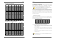
Chapter 2 2-4 Connector and Jumper Reference Chart Chapter 2 2-5 Connector and Jumper Settings Connectors are used to link the system board with other parts of the system, Jump Connector Function Page PW 1 u-ATX Power Supply Connector 10 FD1 Floppy Connector 11 IDE 1/2 IDE Hard-Disk Connector 12 FAN 1/3 CPU/ Case FAN Connector (12V) 12 FAN 4 North Bridge Cooling Fan Power Connector JP1 CMOS Clear Jumper 13 JP5 Keyboard Power on Function Jumper 14 JP6 Disable/Enable USB 0/1 Device
Chapter 2 Chapter 2 Power-On By Modem: While in Soft-Off state, if an external modem ring-up signal occurs, the system IDE 1/2 (IDE Hard-Disk Connector) wakes up and can be remotely accessed. You may enable this function in BIOS's Power Management Setup menu. (See section 3). Blinking LED in Suspend Mode: While in Suspend mode, the LED light on the front panel of your computer will flash.
Chapter 2 Chapter 2 JP5 (Keyboard Power On Function Jumper): FAN 4 (North Bridge Cooling Fan Power) Pin Definition 1-2 Disable (default) 2-3 This connector is for the north bridge-cooling fan. The wiring and plug may vary depending on the manufacturer. On standard fans, the red wire is positive (+12V), the black wire is ground. Enable This board can be turned on by the PS / 2 keyboard (hot key).
Chapter 2 Chapter 2 JP6A/B (Enable/Disable USB 2/3, 4/5 Device Power ON Jumper) Pin JP25 (Setup CPU FSB. Freq. Jumper) Definition Pin 1-2 Disable (default) 2-3 1-2 Enable 2-3 Definition 133/166 MHz (default) 100 MHz A USB keyboard hot key or a USB mouse click can turn on this motherboard. To This cap setups up the CPU Ext. Clock Frequency. use this function, select [Enable] at the USB Resume from S3 under Wake Up Events in the BIOS's Power Management setup screen.
Chapter 2 Chapter 2 CN3 (Auxiliary Audio-in Connector): the system back to Full-On. Pushing the button while in Full-On mode for more than [4 seconds] will switch the system completely off. See Over-ride Power Button Operation diagram. 2. P-LED (Power LED Connector): The power indicator LED shows the system's power status. It is important to pay attention to the correct cables and pin orientation. (i.e., not to reverse the order of these two connectors.) 3.
Chapter 2 Chapter 2 CN5 [WOL (Wake-on-LAN) Connector]: CN7 (Smart Card Reader Connector): Enable the Wake Up On LAN selection in BIOS's Power Management Setup Menu to use this function. The capability to remotely manage PCs on a network is a This connector must be connected to a Smart card reader, which allows you to significant factor in reducing administrative and ownership costs. Magic Packet transfer data through Smart Cards and Smart Card user interface software.
Chapter 2 Chapter 2 CN24 (Front Audio Connector): CN17 (Blue LED Connector): These features work entirely the same as the power indicator LED, both shows the This connector give you the option of a front panel audio jack cable ext. to be plug system’s power status. The only difference is that this one is blue while the other is into a special custom designed system case. Simply remove the two jumper caps at red LED. pin [5-6] and [9-10] then plug it into the (optional) cable ext. connector.
Chapter 2 Chapter 3 Chapter 3 BIOS Setup Program COM 2 (Serial port / COM Headers) Phoenix-Award BIOS ROM has a built-in setup program that allows users to modify the basic system configuration. This information is stored in CMOS RAM so that it can retain the setup information, even when the power is turned off. To enter the Phoenix-Award BIOS setup program press the [Delete key] when you Power on or reboot the computer system.
Chapter 3 Chapter 3 3-2 Advanced BIOS Features 3-1 Standard CMOS Features The Standard CMOS Features allows users to configure system components such as hard disk drive, floppy disk drive and video display as well as date, time and boot-up error signaling. This configuration menu should be changed when installing a By choosing the Advanced BIOS Features option from the CMOS Setup Utility menu (Figure 3-1), the screen below is displayed.
Chapter 3 completes. BIOS will search these drives for an operating system. Swap Floppy Drive Enabling this function will swap the floppy drive assignment so that drive A will function as drive B, and drive B will function as drive A. Note that the boot sequence Chapter 3 Controller). Due to compliance to PC2001 design guide, the system is able to run in APIC mode. Enabling APIC mode will expand available IRQs resources for the system. Available options are [Enabled] and [Disabled].
Chapter 3 3-3 Advanced Chipset Features By choosing the [Advanced Chipset Features] option from the CMOS Setup Utility menu (Figure 3-1), the screen below is displayed. This sample screen contains the Chapter 3 CPU Interface This option allows you to determine how your CPU interface performs. Available options are: [Optimal] and [Aggressive] there details are as follows: Optimal: Select this option will let the system automatically detect its performance.
Chapter 3 which is not in use, will be available for the system. For example, if 16MB is allotted to the AGP card and the card only needs 8MB, the remaining 8MB will be available for system use. Chapter 3 3-4 Integrated Peripherals This section provides information on setting peripheral devices. By choosing the Integrated Peripherals option from the CMOS Setup Utility menu (Figure 3-1), the AGP Frequency This function determines the amount of AGP frequency that is given to the AGP card.
Chapter 3 Chapter 3 parallel port. 5. IDE HDD Block Mode: Block mode is also called block transfer, multiple commands, or multiple sector 6. Parallel Port Mode: read/write. If your IDE hard drive supports block mode, select Enabled to Select an operating mode for the onboard parallel (printer) port. Select SPP unless auto-detect the optimal number of block read/writes per sector the drive can support. you are certain your hardware and software support one of the other available modes.
Chapter 3 Chapter 3 1. Blank Screen - BIOS will only blank the monitor's screen. The electricity saved in 3-5 Power Management Setup this mode is negligible and this function is only used as a screen saver to prevent This section provides information on the Green PC power management functions. By screen damage while the screen is on but not in use. choosing the Power Management Setup option from the CMOS Setup Utility menu 2.
Chapter 3 signal and wake up the system from soft off and green mode. You should connect the modem to the COM port and call your PC to power on. Chapter 3 3-6 PNP/PCI Configurations This section provides IRQ and DMA setting information. By choosing the PNP/PCI 3. USB Resume from S3 The option will allow the activity of USB device to wake up the system from S3 power saving modes. Settings are [Enabled] and [Disabled].
Chapter 3 3-7 PC Health Status By choosing the PC Health Status option from the CMOS Setup Utility menu (Figure 3-1), the screen below is displayed. This field shows you the current CPU temperature/external voltages input and the current CPU FAN operating speed. Chapter 3 3-8 Frequency/Voltage Control By choosing the Frequency/Voltage Control option from the CMOS Setup Utility menu (Figure 3-1), the screen below is displayed.
Chapter 3 Chapter 3 3-9 Load Fail-Safe Defaults 3-12 Save and Exit Setup Load Fail-Safe Defaults loads the default BIOS values directly from the CMOS Setup If you select this and type [Y] (for Yes) followed by the [Enter] key, the values entered in the setup utilities will be recorded in the CMOS memory of the BIOS chip. Utility menu (Figure3-1).
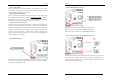
Chapter 4 Chapter 4 3. Please, click [OK] to continue. Chapter 4 DRIVER Setup Please insert the nVidia Series driver CD into the CD-ROM. 4. To restart you computer now, select [Yes, I want to restart my computer now.] then Please Click [OK] to restart you computer. If you do not want to restart your computer select [No, I will restart my computer later.] then click [OK] to continue. 4-1 Nvidia Driver Package Setup 1. Please, select [Nvidia Driver Package] to begin installation. 2.
Chapter 4 Chapter 4 3. To restart you computer now, select [Yes, I want to restart my computer now.] then Please Click [OK] to restart you computer. If you do not want to restart your computer select [No, I will restart my computer later.] then click [OK] to continue. 4-2 VIDEO Application 1. Please, select [Audio Drive] to begin installation. 2.
Chapter 4 Chapter 4 3. Please, click [Next>] to continue install the C-Media Audio driver. 4-3 Audio driver 4. Please, click [Next>] to continue install the C-Media Audio driver. 1. Please, select [Audio Drive] to begin installation. 2. Please, click [NEXT>] to start installation.
Chapter 4 Chapter 4 5. Please, click [Next>] to continue install the C-Media Audio driver. 7. To restart you computer now, select [Yes, I want to restart my computer now.] then Please Click [OK] to restart you computer. If you do not want to restart your computer select [No, I will restart my computer later.] then click [OK] to continue. 6. Please, click [Next>] to continue install the C-Media Audio driver. 4-4 USB 2.0 Driver Setup By Choosing [USB 2.
Chapter 5 Chapter 5 `0`(zero) and o (letter `O`)). Then run the flash utility. Chapter 5 How to update your BIOS? On the screen the program will ask for the [File Name to Program]. Type in the Updating BIOS may result an unstable system. All the data of the old BIOS exact name of the BIOS update binary file, including the *.BIN, and press will be replaced by the new BIOS. Should anything go wrong during the [ENTER].
Note NOTE How To Contact CHAINTECH How To Contact CHAINTECH Please do not hesitate to contact us if you have any problem about our products. Any opinion will be appreciated. All rights are reserved for the products and corporate names/logos that appear in this manual to their original owners. Rights are reserved for changing this manual. All information is subject to change without notice. For Asia, Africa, Australia and Pacific Island: For America: CHAINTECH COMPUTER CO.