Declaration of Conformity AMD® Socket A According to 47 CFR, Parts 2 and 15 of the FCC Rules NVIDIA nForce 2 IGP+ MCP The following designated product: u-ATX Motherboard EQUIPMENT: MAINBOARD is a Class B digital device that complies with 47 CFR Parts 2 and 15 of the FCC Rules. Operation is subject to the following two conditions: User’s Guide 1. This device may not cause harmful interference. 2.
Federal Communications Commission Statement This device complies with FCC Rules Part 15. Operation is subject to the following two conditions: * This device may not cause harmful interference. * This device must accept any interference received, including interference that may cause undesired operation. This equipment has been tested and found to comply with the limits for a Class B digital device, pursuant to TABLE OF CONTENTS Chapter 1 Introduction ........................................................
Chapter 1 Chapter 1 Chapter 1 Introduction 1-1 Product Specifications Supports AMD Socket A Duron / Athlon / Athlon XP processors - System Clock supports 200 / 266 / 333 / 400 MHz Front Side Bus Supports USB 2.0 high-speed device @480 Mb/s transfer rates - ITE 8712 LPC I/O with system monitors hardware - Two UARTs support serial ports and IR function (up to 115.2Kbps) for HPSIR and ASKIR Chipset - Supports total six USB 2.0 Ports (USB 1.
Chapter 1 1-3 Motherboard Diagram Chapter 1 1-4 Motherboard Layout 3 4
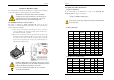
Chapter 2 Chapter 2 2-2 Setting Your CPU’s Performance: Chapter 2 Hardware Setup Frequency Configuration: If you install a CPU on this motherboard, you must set the [Front Side Bus If your motherboard has already been installed in your computer you may still need to refer to this chapter if you plan to upgrade your system’s hardware. Frequency] JP25 according to your processor. This motherboard is electrostatic sensitive.
Chapter 2 Chapter 2 1000 1000MHz 100 10.0 1.75V 256KB 0.18 2-3 Main Memory Configuration 1100 1100MHz 100 11.0 1.75V 256KB 0.18 This motherboard provides 3 184pin Double Data Rate (DDR) Dual Inline Memory 1200 1200MHz 100 12.0 1.75V 256KB 0.18 Modules (DIMM) slots. Which supports PC 1600/DDR200, PC2100/DDR266, 1300 1300MHz 100 13.0 1.75V 256KB 0.18 PC2700/DDR333 and PC3200/DDR400 DDR SDRAM modules up to 3GB. 1400 1400MHz 100 14.0 1.75V 256KB 0.18 1000 1000MHz 133 7.
Chapter 2 2-4 Connector and Jumper Reference Chart Chapter 2 2-5 Connector and Jumper Settings Connectors are used to link the system board with other parts of the system, Jump Connector Function Page PW 1 u-ATX Power Supply Connector 10 FD1 Floppy Connector 11 IDE 1/2 IDE Hard-Disk Connector 12 FAN 1/3 CPU/ Case FAN Connector (12V) 12 FAN 4 North Bridge Cooling Fan Power Connector JP1 CMOS Clear Jumper 13 JP5 Keyboard Power on Function Jumper 14 JP6 Disable/Enable USB 0/1 Device
Chapter 2 Chapter 2 Power-On By Modem: While in Soft-Off state, if an external modem ring-up signal occurs, the system IDE 1/2 (IDE Hard-Disk Connector) wakes up and can be remotely accessed. You may enable this function in BIOS's Power Management Setup menu. (See section 3). Blinking LED in Suspend Mode: While in Suspend mode, the LED light on the front panel of your computer will flash.
Chapter 2 Chapter 2 JP5 (Keyboard Power On Function Jumper): FAN 4 (North Bridge Cooling Fan Power) Pin Definition 1-2 Disable (default) 2-3 This connector is for the north bridge-cooling fan. The wiring and plug may vary depending on the manufacturer. On standard fans, the red wire is positive (+12V), the black wire is ground. Enable This board can be turned on by the PS / 2 keyboard (hot key).
Chapter 2 Chapter 2 JP6A/B (Enable/Disable USB 2/3, 4/5 Device Power ON Jumper) Pin JP25 (Setup CPU FSB. Freq. Jumper) Definition Pin 1-2 Disable (default) 2-3 1-2 Enable 2-3 Definition 133/166/200 MHz (default) 100 MHz A USB keyboard hot key or a USB mouse click can turn on this motherboard. To This cap setups up the CPU Ext. Clock Frequency. use this function, select [Enable] at the USB Resume from S3 under Wake Up Events in the BIOS's Power Management setup screen.
Chapter 2 Chapter 2 CN3 (Auxiliary Audio-in Connector): the system back to Full-On. Pushing the button while in Full-On mode for more than [4 seconds] will switch the system completely off. See Over-ride Power Button Operation diagram. 2. P-LED (Power LED Connector): The power indicator LED shows the system's power status. It is important to pay attention to the correct cables and pin orientation. (i.e., not to reverse the order of these two connectors.) 3.
Chapter 2 Chapter 2 CN5 [WOL (Wake-on-LAN) Connector]: CN7 (Smart Card Reader Connector): Enable the Wake Up On LAN selection in BIOS's Power Management Setup Menu to use this function. The capability to remotely manage PCs on a network is a This connector must be connected to a Smart card reader, which allows you to significant factor in reducing administrative and ownership costs. Magic Packet transfer data through Smart Cards and Smart Card user interface software.
Chapter 2 Chapter 2 CN24 (Front Audio Connector): CN17 (Blue LED Connector): These features work entirely the same as the power indicator LED, both shows the This connector give you the option of a front panel audio jack cable ext. to be plug system’s power status. The only difference is that this one is blue while the other is into a special custom designed system case. Simply remove the two jumper caps at red LED. pin [5-6] and [9-10] then plug it into the (optional) cable ext. connector.
Chapter 2 Chapter 3 Chapter 3 BIOS Setup Program COM 2 (Serial port / COM Headers) Phoenix-Award BIOS ROM has a built-in setup program that allows users to modify the basic system configuration. This information is stored in CMOS RAM so that it can retain the setup information, even when the power is turned off. To enter the Phoenix-Award BIOS setup program press the [Delete key] when you Power on or reboot the computer system.
Chapter 3 Chapter 3 IDE (Primary/Secondary; Master/Slave): This category identifies up to four IDE hard disk drives that have been installed in the First/Second/Third/Boot Other Device: This option sets the sequence of drives BIOS attempts to boot from after POST computer. This section does not show information on other IDE devices such as completes. BIOS will search these drives for an operating system. CD-ROM drives or other hard drive type such as SCSI drives.
Chapter 3 APIC Mode This item can enable or disable the APIC (Advanced Programmable Interrupt Controller). Due to compliance to PC2001 design guide, the system is able to run in APIC mode. Enabling APIC mode will expand available IRQs resources for the system. Available options are [Enabled] and [Disabled]. Chapter 3 System Performance. This option allows you to configure and determine your systems performance according to your needs.
Chapter 3 Expert: Select this option only if you are a professional user. This will allow you to manually adjust the memory timing according to your needs. Chapter 3 Video RAM Cacheable Enabling this function will allows caching of the video RAM, resulting in better Overclocking: system performance. However, if any programs write to this memory area, a system This motherboard is designed to support overclocking. However, please make error may occur.
Chapter 3 Chapter 3 4. IDE Prefetch Mode: 4. UR2 Duplex Mode: The onboard IDE drive interfaces supports prefetching, for faster drive accesses. Set This allows you to adjust the way of InfraRed transmitting. Available options are to [Disabled] if this primary or secondary. [Half] which will only receive/send then it will send/receive and [Full] which will receive and send at the same time. 5. IDE HDD Block Mode: Block mode is also called block transfer, multiple commands, or multiple sector 5.
Chapter 3 3-5 Power Management Setup Chapter 3 This section provides information on the Green PC power management functions. By HDD Power Down: Shuts down any IDE hard disk drives in the system after a period of inactivity as set in choosing the Power Management Setup option from the CMOS Setup Utility menu this user configurable field. This feature does not affect SCSI hard drives. (Figure 3-1), the screen below is displayed.
Chapter 3 Chapter 3 3-7 PC Health Status 5. POWER ON Function: This control show the PS/2 mouse or keyboard can power on the system. Available By choosing the PC Health Status option from the CMOS Setup Utility menu (Figure settings are [Password], [Hot KEY], [Mouse Move], [Mouse Click], [Any Key], 3-1), the screen below is displayed. This field shows you the current CPU [BUTTON ONLY] and [Keyboard 98]. temperature/external voltages input and the current CPU FAN operating speed. 6.
Chapter 3 Chapter 4 3-11 Supervisor Password & User Password Setting There are four different variables that control password settings. Chapter 4 DRIVER Setup The first two are located under the Security Option function in BIOS Features Setup Menu (Figure 3-1). Please insert NVIDIA Series driver CD into the CD-ROM. When the Security Option function is set to Setup, a password is required to enter BIOS and change BIOS settings.
Chapter 4 Chapter 5 For Windows XP installation: Chapter 5 How to update your BIOS? 1. Select [Control Panel] and choose [System]. 2. Select [Hardware] folder and then click on [Device Manger]. Updating BIOS may result an unstable system. All the data of the old BIOS 3. Select [Universal Serial Bus (USB) Controller]. will be replaced by the new BIOS. Should anything go wrong during the 4. Select [Reinstall Driver] updating process, your system would end up crashed. Please refer to your 5.
Chapter 5 Note 7. Run the FLASH utility Make sure the BIOS update binary file is in the same directory as the FLASH NOTE utility. Remember the exact name of the BIOS update file. (Please pay attention to `0`(zero) and o (letter `O`)). Then run the flash utility. On the screen the program will ask for the [File Name to Program]. Type in the exact name of the BIOS update binary file, including the *.BIN, and press [ENTER]. The program will now ask you if you want to save your current BIOS version.
How to Contact CHAINTECH How To Contact CHAINTECH Please do not hesitate to contact us if you have any problem about our products. Any opinion will be appreciated. For Asia, Africa, Australia and Pacific Island: CHAINTECH COMPUTER CO., LTD No. 7-1, Chung Shin Rd., Tu Cheng, Taipei Hsien, Taiwan, ROC. Tel: +886-2-2268-9998 Fax: +886-2-2269-7510 URL: http://www.chaintech.com.tw E-mail: sales@chaintech.com.tw For Italy and Southern Europe: CELT COMPUTER s.r.l.