7ZX-1 TM AMD Athlon /Duron TM Socket A Motherboard USER'S MANUAL AMD AthlonTM/DuronTM Socket A Processor Motherboard REV. 1.
FCC Compliance Statement: DECLARATION OF CONFORMITY Per FCC Part 2 Section 2. 1077(a) Responsible Party Name: G.B.T. INC. Address: 18305 Valley Blvd., Suite#A LA Puent, CA 91744 Phone/Fax No: (818) 854-9338/ (818) 854-9339 hereby declares that the product Product Name: Mother Board Model Number: GA-7ZX Conforms to the following specifications: FCC Part 15, Subpart B, Section 15.107(a) and Section 15.
Declaration of Conformity We, Manufacturer/Importer (full address) G.B.T.
Table Of Content SUMMARY OF FEATURES................................................................................................................................ 2 7ZX-1 MOTHERBOARD LAYOUT ................................................................................................................... 3 CPU SPEED SETUP ............................................................................................................................................. 4 CONNECTORS................................
PNP/PCI CONFIGURATIONS ............................................................................................................................... 30 LOAD BIOS DEFAULTS ...................................................................................................................................... 31 LOAD SETUP DEFAULTS ..................................................................................................................................... 32 INTEGRATED PERIPHERALS .....................
7ZX-1 Motherboard Revision History Revision 1.01 Revision Note Initial release of the 7ZX-1 motherboard user’s manual. Date Dec.2000 The author assumes no responsibility for any errors or omissions that may appear in this document nor does the author make a commitment to update the information contained herein. Third-party brands and names are the property of their respective owners. DEC. 11, 2000 TAIPEI, TAIWAN, R.O.
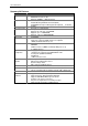
ZX-1 Motherboard Summary Of Features Form Factor CPU Chipset Clock Generator Memory I/O Control Slots On-Board IDE 30.5 cm x 22.8 cm ATX size form factor, 4 layers PCB.
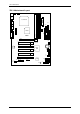
7ZX-1 Motherboard 7ZX-1 Motherboard Layout JP4 J3 ATX POWER USB1 PS/2 JP6 LPT COM A Socket A CPU FLOPPY COM B JP8 J15 LED1 JP7 IDE2 IDE1 DIMM3 DIMM2 7ZX-1 DIMM1 J18 GAME & AUDIO VT8363 AGP 1 SW1 Clock Generator AD1881 PCI1 PCI2 BAT1 VT82C 686A J13 PCI3 JP3 J12 JP10 PCI4 J2 PCI5 BIOS JP16 AMR USB2 J4 JP17 BZ1 3 J11 JP11 JP9 JP18
7ZX-1 Motherboard CPU Speed Setup The system bus speed is selectable at 100~133MHz. The user can select the system bus speed by DIP switch SW1. Set System Bus Speed zIf your clock generator (in Motherboard) is ICS 9248-141. You can follow the below reference. ICS 9248-141 SW1: (ICS 9248-141) O : ON, X : OFF FSB 95 Ë100 105 110 113 115 117 133 3 X X O O O X O X 1 O X X O X X X X 2 O O O X X X X X 4 O X X X O O X X zIf your clock generator (in Motherboard) is ICW W230H.
Connectors Connectors Game & Audio Port Game Port Line Out 1 MIC In Line In COM A / COM B / LPT Port LPT Port COM A COM B USB 1 Connector 1 2 34 5 67 8 Pin No.
Connectors USB 2 Connector 2 10 1 9 Pin No. 1 2 3 4 5 6 7 8 9 10 Definition +5V GND USB D2NC USB D2+ USB D3+ NC USB D3GND +5V PS/2 Keyboard & PS/2 Mouse Connector PS/2 Mouse/Keyboard Pin No. Definition 1 Data 5 6 2 NC 3 4 3 GND 4 VCC(+5V) 2 1 5 Clock PS/2 Keyboard 6 NC PS/2 Mouse J3: CPU Fan 1 Pin No.
7ZX-1 Motherboard JP6: Power Fan 1 Pin No. Definition 1 Control 2 +12V 3 NC J2: Sysem Fan 1 Pin No. Definition 1 Control 2 +12V 3 SENSE ATX Power 10 20 1 11 Pin No. Definition 3,5,7,13, GND 15-17 1,2,11 3.
Connectors Floppy Port Red Line FDD1 IDE1(Primary), IDE2(Secondary) Port Red Line IDE 1 IDE 2 J15: AUX_IN 1 Pin No.
7ZX-1 Motherboard J18: CD Audio Line In 1 Pin No. 1 2 3 4 Definition CD-L GND GND CD-R J13: Ring Power On (Internal Modem Card Wake Up) 1 Pin No. Definition 1 Signal 2 GND J12: Wake On LAN 1 Pin No.
Connectors JP8 / LED1: STR LED Connector & DIMM LED STR LED Connector External. 1 + DIMM LED J4: IR 1 Pin No.
7ZX-1 Motherboard Panel And Jumper Definition J11: 2x11 Pins Jumper GN SPK HD RE 1 1 1 1 P−P−P+ GN (Green Switch) GD (Green LED) HD (IDE Hard Disk Active LED) SPK (Speaker Connector) RE (Reset Switch) P+P−P−(Power LED) PW (Soft Power Connector) GD PW Open: Normal Operation Close: Entering Green Mode Pin 1: LED anode(+) Pin 2: LED cathode(−) Pin 1: LED anode(+) Pin 2: LED cathode(−) Pin 1: VCC(+) Pin 2- Pin 3: NC Pin 4: Data(−) Open: Normal Operation Close: Reset Hardware System Pin 1: LED anod
Panel and Jumper Definition JP4: Rear USB Device Wake up Selection (USB Connector USB1) 1 Pin No. Definition 1-2 Close Normal (Default) 2-3 Close USB Device Wake up USB1 (If you want to use "USB Dev Wakeup From S3-S5" function, you have to set the BIOS setting "USB Dev Wakeup From S3-S5" enabled, and the jumper "JP4" enabled). *(Power on the computer and as soon as memory counting starts, press . You will enter BIOS Setup.
7ZX-1 Motherboard JP11: Front USB Device Wake up Selection (USB Port USB2) 1 USB2 Pin No. Definition 1-2 close Normal (Default) Enabled Front USB Device 2-3 close Wake up (If you want to use "USB Dev Wakeup From S3-S5" function, you have to set the BIOS setting "USB Dev Wakeup From S3-S5" enabled, and the jumper "JP11" enabled). *(Power on the computer and as soon as memory counting starts, press . You will enter BIOS Setup.
Panel and Jumper Definition BAT1: Battery + CAUTION ☞ Danger of explosion if battery is incorrectly replaced. ☞ Replace only with the same or equivalent type recommended by the manufacturer. ☞ Dispose of used batteries according to the manufacturer’s instructions.
Performance List Performance List The following performance data list is the testing results of some popular benchmark testing programs. These data are just referred by users, and there is no responsibility for different testing data values gotten by users. (The different Hardware & Software configuration will result in different benchmark testing results.
7ZX-1 Motherboard Block Diagram 100MHz Socket A AGP 2X/4X System Bus 100MHz VT8363 3.3V SDRAM 100 / 133MHz 66MHz 100 / 133MHz 100 / 133MHz 66MHz 33MHz ICS 9248-141 or ICW W230H 33MHz 5 PCI ATA66 IDE Channels 33MHz 14.
Suspend to RAM Installation Suspend To RAM Installation A.1 Introduce STR function: Suspend-to-RAM (STR) is a Windows 98 ACPI sleep mode function. When recovering from STR (S3) sleep mode, the system is able, in just a few seconds, to retrieve the last “state” of the system before it went to sleep and recover to that state. The “state” is stored in memory (RAM) before the system goes to sleep.
Suspend to RAM Installation B. Choose the “Stand by” item and press “OK” 2. Define the system ”power on” button to initiate STR sleep mode: A. Double click “My Computer” and then “Control Panel” B. Double click the “ Power Management” item.
7ZX-1 Motherboard C. Select the “Advanced” tab and “Standby” mode in Power Buttons. D. Restart your computer to complete setup. Now when you want to enter STR sleep mode, just momentarily press the “Power on” button. A.4 How to recover from the STR sleep mode? There are five ways to “wake up” the system: 1. 2. 3. 4. 5. Press the “Power On” button. Use the “Resume by Alarm” function. Use the “Modem Ring On” function. Use the “Wake On LAN” function. Use the “USB Device Wake Up” function. A.5 Notices: 1.
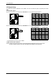
7ZX-1 Motherboard Memory Installation The motherboard has 3 dual inline memory module (DIMM) sockets. The BIOS will automatically detects memory type and size. To install the memory module, just push it vertically into the DIMM Slot .The DIMM module can only fit in one direction due to the two notch. Memory size can vary between sockets.
7ZX-1 Motherboard BIOS Setup BIOS Setup is an overview of the BIOS Setup Program. The program that allows users to modify the basic system configuration. This type of information is stored in battery-backed CMOS RAM so that it retains the Setup information when the power is turned off. ENTERING SETUP Power ON the computer and press immediately will allow you to enter Setup.
BIOS Setup The Main Menu Once you enter AMI BIOS CMOS Setup Utility, the Main Menu (Figure 1) will appear on the screen. The Main Menu allows you to select from nine setup functions and two exit choices. Use arrow keys to select among the items and press to accept or enter the sub-menu. AMIBIOS SIMPLE SETUP UTILITY-VERSION 1.23 ( C ) 1999 American Megatrends, Inc.
7ZX-1 Motherboard • User password Change, set, or disable password. It allows you to limit access to the system. • IDE HDD auto detection Automatically configure hard disk parameters. • Save & Exit Setup Save CMOS value settings to CMOS and exit setup. • Exit Without Saving Abandon all CMOS value changes and exit setup. Standard CMOS Setup The items in Standard CMOS Features Menu (Figure 2) are divided into 9 categories. Each category includes no, one or more than one setup items.
BIOS Setup form your hard disk vendor or the system manufacturer. CYLS. Number of cylinders HEADS number of heads PRECOMP write precomp LANDZONE Landing zone SECTORS number of sectors If a hard disk has not been installed select NONE and press . • Floppy Drive A / Drive B The category identifies the types of floppy disk drive A or drive B that has been installed in the computer. None 360K, 5.25 in. 1.2M, 5.25 in. 720K, 3.5 in. 1.44M, 3.5 in. 2.88M, 3.5 in. No floppy drive installed 5.
7ZX-1 Motherboard BIOS Features Setup AMIBIOS SETUP – BIOS FEATURES SETUP ( C ) 1999 American Megatrends, Inc. All Rights Reserved 1st Boot Device Floppy 2nd Boot Device CDROM 3rd Boot Device IDE-0 S.M.A.R.T.
BIOS Setup Chipset Features Setup AMIBIOS SETUP – CHIPSET FEATURES SETUP ( C ) 1999 American Megatrends, Inc. All Rights Reserved *********DRAM Timing*** CAS# Drive DRAM Frequency Auto RAS# Drive SDRAM CAS# Latency Auto AGP Mode AGP Comp. Driving Manual AGP Comp.
7ZX-1 Motherboard • USB Controller Enabled Disabled Enabled USB Controller. (Default Value) Disabled USB Controller. • USB Legacy Support Keyboard/FD D KB/Mouse/F DD Disabled Set USB Legacy Support Keyboard / Floppy. Set USB Legacy Support Keyboard / Mouse /Floppy. Disabled USB Legacy Support Function. (Default Value) • BIOS Flash Protection Enabled Disabled BIOS Flash Write Protection. Normal. (Default Value) • DRAM Drive Strength Auto Manual Set DRAM Drive Strength Auto.
BIOS Setup Power Management Setup AMIBIOS SETUP – POWER MANAGEMENT SETUP ( C ) 1999 American Megatrends, Inc.
7ZX-1 Motherboard • System after AC Back Function Memory Soft-Off Full-On This function depends on computer status. . (Default Value) Set System Soft-Off Status Set System Full-On Status. • Modem USE IRQ 3, 4, (Default Value) 5, 7, N/A • Resume On Ring / LAN Disabled Enabled Disabled Resume On Ring / LAN. Enabled Resume On Ring / LAN. (Default Value) • PME Event Wake Up Disabled Enabled Disabled PME Event Wake Up. Enabled PME Event Wake Up.
BIOS Setup PnP/PCI Configurations AMIBIOS SETUP – PNP / PCI CONFIGURATION ( C ) 1999 American Megatrends, Inc.
7ZX-1 Motherboard Load BIOS Defaults AMIBIOS SIMPLE SETUP UTILITY-VERSION 1.23 ( C ) 1999 American Megatrends, Inc.
BIOS Setup Load Setup Defaults AMIBIOS SIMPLE SETUP UTILITY-VERSION 1.23 ( C ) 1999 American Megatrends, Inc.
7ZX-1 Motherboard Integrated Peripherals AMIBIOS SETUP – INTEGRATED PERIPHERALS ( C ) 1999 American Megatrends, Inc.
BIOS Setup • Parallel Port Mode EPP ECP Normal EPP+EC P Using Parallel port as Enhanced Parallel Port. Using Parallel port as Extended Capabilities Port. (Default Value) Normal Operation. Using Parallel port as Enhanced Parallel Port & Extended Capabilities Port. • Parallel Port DMA Auto 3 1 0 Set Auto to parallel port mode DMA Channel. (Default Value) Set Parallel Port DMA to 3. Set Parallel Port DMA to 1. Set Parallel Port DMA to 0. • Parallel Port IRQ 7 Auto 5 Set Parallel Port IRQ to 7.
7ZX-1 Motherboard • MPU-401 Enabled Disabled Enabled MPU-401. Disabled MPU-401. (Default Value) Ps. When Force Feedback joystick is used, MPU-401 needs to be Enable. • MPU-401 I/O Address 330h333h 300h303h 310h313h 320h323h Set MPU-401 I/O Address to 330h-333h. (Default Value) Set MPU-401 I/O Address to 300h-303h. Set MPU-401 I/O Address to 310h-313h. Set MPU-401 I/O Address to 320h-323h. • Game Port (200h-207h) Disabled Enabled Disabled Game Port (200h-207h). Enabled Game Port (200h-207h).
BIOS Setup Hardware Monitor AMIBIOS SETUP – HARDWARE MONITOR SETUP ( C ) 1999 American Megatrends, Inc. All Rights Reserved ACPI Shut Down Temp. CPU Temperature System Temperature CPU Fan Speed System Fan Speed Vcore Vdd Vcc3 +5.000V +12.000V Disabled 32°C/89°F 32°C/89°F 7123 RPM 0 RPM 1.76 V 3.33 V 3. 27 V 4.97 V 12.
7ZX-1 Motherboard Set Supervisor / User Password When you select this function, the following message will appear at the center of the screen to assist you in creating a password. AMIBIOS SIMPLE SETUP UTILITY-VERSION 1.23 ( C ) 1999 American Megatrends, Inc.
BIOS Setup IDE HDD AUTO Detection AMIBIOS SETUP – STANDARD CMOS SETUP ( C ) 1999 American Megatrends, Inc. All Rights Reserved Date (mm/dd/yyyy) : Tue Jan 25, 2000 Time (hh/mm/ss) : 10:36:24 TYPE SIZE CYLS HEAD PRECOMP LANDZ SECTOR MODE Pri Master : Not Installed Pri Slave : Not Installed Sec Master : Not Installed Sec Slave : Not Installed Floppy Drive A: 1.
7ZX-1 Motherboard Save & Exit Setup AMIBIOS SIMPLE SETUP UTILITY-VERSION 1.23 ( C ) 1999 American Megatrends, Inc.
BIOS Setup Exit Without Saving AMIBIOS SIMPLE SETUP UTILITY-VERSION 1.23 ( C ) 1999 American Megatrends, Inc.
Appendix Appendix: Acronyms Acronyms ACPI POST LAN ECP APM DMA MHz ESCD CPU SMP USB OS ECC IDE SCI LBA EMC BIOS SMI IRQ NIC A.G.P. S.E.C.C.