Introduction AN9 32X Motherboard AMD Socket AM2 Hardware Setup User’s Manual 2GHz HT Dual DDR2 800 DIMM Slots NVIDIA SLI Technology Dual PCI-E X16 Slots Driver & Utility CD NB: NVIDIA C51XE SB: NVIDIA MCP55PXE BIOS Setup AMD Socket AM2 ATX Motherboard Dual GbE LAN IEEE 1394a 8x SATA 3Gb/s with RAID ABIT Guru™ Technology ABIT Silent OTES™ Technology 7.
AN9 32X User’s Manual English, 1st Edition June, 2006 Copyright and Warranty Notice The information in this document is subject to change without notice and does not represent a commitment on part of the vendor, who assumes no liability or responsibility for any errors that may appear in this manual. No warranty or representation, either expressed or implied, is made with respect to the quality, accuracy or fitness for any particular part of this document.
Introduction Contents 1. Introduction ..................................................................... 1-1 1.1 Features & Specifications .............................................................1-1 1.2 Motherboard Layout.....................................................................1-3 Hardware Setup 2. Hardware Setup ............................................................... 2-1 2.1 Choosing a Computer Chassis .......................................................2-1 2.
3.3 Advanced BIOS Features ............................................................ 3-13 3.4 Advanced Chipset Features......................................................... 3-15 3.5 Integrated Peripherals................................................................ 3-17 3.6 Power Management Setup.......................................................... 3-21 3.7 PnP/PCI Configurations .............................................................. 3-24 3.8 Load Fail-Safe Defaults ..................
Introduction 1. Introduction 1.
• 1x AudioMAX slot Internal I/O Connectors • • • • • 1x 1x 7x 3x 2x Floppy port UDMA 133/100/66/33 connector SATA connectors USB 2.0 headers IEEE1394a headers Rear Panel I/O • • • • • • Silent OTES™ 1x eSATA connector 1x PS/2 Keyboard connector 1x PS/2 Mouse connector 2x RJ-45 Gigabit LAN ports 4x USB 2.
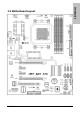
Introduction 1.
1-4 AN9 32X
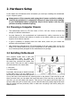
2. Hardware Setup In this chapter we will elaborate all the information you need upon installing this motherboard to your computer system. ※ Always power off the computer and unplug the AC power cord before adding or removing any peripheral or component. Failing to so may cause severe damage to your motherboard and/or peripherals. Plug in the AC power cord only after you have carefully checked everything. • This motherboard carries an ATX form factor of 305 x 245 mm.
1. Locate all the screw holes on the motherboard and the chassis base. 2. Place all the studs or spacers needed on the chassis base and have them tightened. 3. Face the motherboard’s I/O ports toward the chassis’s rear panel. 4. Line up all the motherboard’s screw holes with those studs or spacers on the chassis. 5. Install the motherboard with screws and have them tightened. Face the chassis’s rear panel.
2.3.1 CMOS Memory Clearing Header and Backup Battery The time to clear the CMOS memory occurs when (a) the CMOS data becomes corrupted, (b) you forgot the supervisor or user password preset in the BIOS menu, (c) you are unable to boot-up the system because the CPU ratio/clock was incorrectly set in the BIOS menu. This header uses a jumper cap to clear the CMOS memory and have it reconfigured to the default values stored in BIOS. Pins 1 and 2 shorted (default): Normal operation.
CMOS Backup Battery: An onboard battery saves the CMOS memory to keep the BIOS information stays on even after disconnected your system with power source. Nevertheless, this backup battery exhausts after some five years. Once the error message like “CMOS BATTERY HAS FAILED” or “CMOS checksum error” displays on monitor, this backup battery is no longer functional and has to be renewed. To renew the backup battery: 1. Power off the system and disconnect with AC power source. 2. Remove the exhausted battery.
2.3.2 Wake-up Headers These headers use a jumper cap to enable/disable the wake-up function. Hardware Setup • PS2-PWR1: Pin 1-2 shorted (Default): Disable wake-up function support at Keyboard/Mouse port. Pin 2-3 shorted: Enable wake-up function support at Keyboard/Mouse port. • USB-PWR1: Pin 1-2 shorted (Default): Disable wake-up function support at USB1 port. Pin 2-3 shorted: Enable wake-up function support at USB1 port.
2.4 Connecting Chassis Components 2.4.1 ATX Power Connectors These connectors provide the connection from an ATX power supply. As the plugs from the power supply fit in only one orientation, find the correct one and push firmly down into these connectors. ATX 24-Pin Power Connector: The power supply with 20-pin or 24-pin cables can both be connected to this 24-pin connector. Connect from pin-1 for either type.
2.4.2 Front Panel Switches & Indicators Headers This header is used for connecting switches and LED indicators on the chassis front panel. Watch the power LED pin position and orientation. The mark “+” align to the pin in the figure below stands for positive polarity for the LED connection. Please pay attention when connecting these headers. A wrong orientation will only cause the LED not lighting, but a wrong connection of the switches could cause system malfunction.
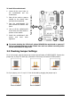
2.4.3 FAN Power Connectors These connectors each provide power to the cooling fans installed in your system. • CPUFAN1: CPU Fan Power Connector • SYSFAN1: System Fan Power Connector • AUXFAN1~4: Auxiliary Fan Power Connector ※ These fan connectors are not jumpers. DO NOT place jumper caps on these connectors.
2.5 Installing Hardware ※ DO NOT scratch the motherboard when installing hardware. An accidentally scratch of a tiny surface-mount component may seriously damage the motherboard. 2.5.1 CPU Socket AM2 ※ DO NOT touch or bend the delicate pins on the CPU whenever you are holding it. 1. Pull out the socket lever away from the socket and fully lift it up over 90-degree angle. Locate and align the triangle mark with both the CPU and the socket body.
4. Place the heatsink and fan assembly onto the retention frame. Match the heatsink clip with the socket mounting-lug. Hook the spring clip to the mounting-lug. 5. On the other side, push the retention clip straight down to lock into the plastic lug on the retention frame. 6. Connect the CPU cooling fan power cable to the CPUFAN1 connector on this motherboard. ※ The “CPUFAN1” connector MUST be connected with cooling fan, no matter a 3-Pin or 4-Pin CPU Fan.
2.5.2 DDR2 Memory Slots This motherboard provides four 240-pin DIMM slots for Dual Channel DDR2 800 memory modules with memory expansion size up to 8GB. Hardware Setup To reach the performance of Dual Channel DDR2, the following rules must be obeyed: • For a 2-DIMM dual-channel installation: Populate DIMM modules of the same type and size on slots [DIMM1]+[DIMM2], or slots [DIMM3]+[DIMM4].
To install system memory: 1. Power off the computer and unplug the AC power cord before installing or removing memory modules. 2. Locate the DIMM slot on the board. 3. Hold two edges of the DIMM module carefully, keep away from touching its connectors. 4. Align the notch key on the module with the rib on the slot. 5. Firmly press the module into the slots until the ejector tabs at both sides of the slot automatically snap into the mounting notch.
Two PCIE graphics cards installation (SLI Mode): To install two SLI-ready graphics cards under SLI Mode, you will need to: • Prepare two identical NVIDIA certified, SLI-ready PCI Express x16 graphics cards (the same model from the same manufacturer). • Make sure the graphics card driver supports the NVIDIA SLI technology. Download the latest driver form NVIDIA website (www.nvidia.com). • Make sure your power supply unit is sufficient to provide the minimum power required. 1.
2.5.4 AudioMAX Connection Slot This slot provides the audio input/output connection over the rear I/O part through an add-on daughter-card. Find your “AudioMAX” daughter-card and its driver in the motherboard package. • S/PDIF Out: This connector provides an S/PDIF-Out connection through optical fiber to digital multimedia devices. • S/PDIF In: This connector provides an S/PDIF-In connection through optical fiber to digital multimedia devices.
• FP-AUDIO1: This header provides the connection to audio connector at front panel. This header provides the front panel connection for HD (High Definition) Audio, yet for AC’97 Audio CODEC connection, you must carefully check the pin assignment before connecting from the front panel module. An incorrect connection may cause malfunction or even damage the motherboard.
3. Click “Disabled front panel jack detection”, and then click “OK” to confirm. S/PDIF Connection: In the motherboard package you can find one audio daughter-card and one optical-fiber cable. • S/PDIF Input Connection: 1. Remove the rubber protection-cap. Attach one end of the optical cable with the 3.5mm Optical-to-Stereo adapter, and have it plugged into the [Line-In] jack on this daughter-card. (This jack is served for either optical or line input.) 2.
2.6 Connecting Peripheral Devices 2.6.1 Floppy and IDE Disk Drive Connectors Hardware Setup The FDC1 connector connects up to two floppy drives with a 34-wire, 2-connector floppy cable. Connect the single end at the longer length of ribbon cable to the FDC1 on the board, the two connectors on the other end to the floppy disk drives connector. Generally you need only one floppy disk drive in your system.
2.6.2 Serial ATA Connectors Each SATA connector serves as one single channel to connect one SATA device by a thin SATA cable. • SATA1~SATA6: Available for RAID 0, RAID 1, RAID 0+1, RAID 5, or RAID 10 configuration by the utility “Intel Matrix Storage Manager”. • SATA7、eSATA1: Available for RAID 0 or RAID 1 configuration by the utility “Sil3132 SATA RAID Driver”. To connect SATA device: 1. Attach either end of the signal cable to the SATA connector on motherboard. Attach the other end to SATA device. 2.
2.6.3 Additional USB 2.0 Port Headers Besides the 4x USB 2.0 ports located at rear I/O part, this motherboard also features 3x more USB 2.0 headers onboard. Each header supports 2x additional USB 2.0 ports by connecting bracket or cable to the rear I/O panel or the front-mounted USB ports of your chassis. Pin Assignment Pin 1 VCC 2 Pin Assignment VCC 3 Data0 - 4 Data1 - 5 Data0 + 6 Data1 + 7 Ground 8 Ground 10 NC ※ Make sure the connecting cable bears the same pin assignment. 2.6.
2.6.5 PCI Express X1 Add-on Slots These slots provide the connection of add-on cards that comply with PCI Express specifications. 2.6.6 PCI Add-on Slot This slot provides the connection of add-on cards that comply with PCI specifications.
2.6.7 GURU Panel Connection Header This header is reserved for connecting ABIT’s exclusive GURU Panel. For more information, please refer to the included GURU Panel Installation Guide.
2.7 Onboard Status Display 2.7.1 POST Code Displayer This is an LED device to display the “POST” Code, the acronym for Power On Self Test. The computer will execute the POST action whenever you power on the computer. The POST process is controlled by the BIOS. It is used to detect the status of the computer’s main components and peripherals. Each POST Code corresponds to different checkpoints that are also defined by the BIOS in advance.
2.7.2 Power Source Indicators These indicators work as a reminding device to display the power status of this motherboard with power source connected. • 5VSB: Lights On: Your ATX power supplier is connected with power source, and its power switch is on. • VCC: Lights On: The system power is on. Lights Off: The system power is off. • SLI_PWR1: Lights On: The system power is on. Lights Off: The “ATX4P1” connector is connected with power source from your ATX power supplier.
2.8 Connecting I/O Devices • Silent OTES™: The Silent OTES™ (Silent Outside Thermal Exhaust System) is a device specifically designed to silently cool the motherboard's North Bridge chipset. (Keep the area for outgoing heat wave open.) • eSATA1: This connector supports the external SATA connection. • Mouse: Connects to PS/2 mouse. • Keyboard: Connects to PS/2 keyboard. • LAN1/LAN2: Connects to Local Area Network.
3. BIOS Setup This motherboard provides a programmable EEPROM so that you can update the BIOS utility. The BIOS (Basic Input/Output System) is a program that deals with the basic level of communication between processor and peripherals. Use the BIOS Setup program only when installing motherboard, reconfiguring system, or prompted to “Run Setup”. This chapter explains the Setup Utility of BIOS utility.
3.1 µGuru™ Utility There are two setup menus in this µGuru utility. You may switch between these two by clicking the left or right arrow key on keyboard: 3.1.1 OC Guru µGuru Utility V1.00 OC Guru AMD Athlon(tm) 64 X2 Dual Core Processor 3800+ Frequency : 2000MHz CPU Operating Speed X - Multiplier Factor X - External Clock X - PCIE Clock X X X X X X X Voltages Control - CPU Core Voltage - DDR2 Voltage - NB 1.2V Voltage - NB PCIE 1.2V Voltage - SB 1.
- Multiplier Factor This item displays the multiplier factor for the CPU you installed. - External Clock This item selects the external clock frequency. Due to the specification limit of the CPU you installed, the speed you set over its standard bus speed is supported, but not guaranteed. - PCIE Clock This item selects the clock frequency for PCI Express slot. Voltages Control This option allows you to switch between the default and user-defined voltages.
3.1.2 ABIT EQ Click right-arrow <→> key to switch from OC Guru setup menu to ABIT EQ setup menu: µGuru Utility V1.00 ► ► ► ► ABIT EQ ABIT EQ Beep Control Temperature Monitoring Voltage Monitoring Fan Speed Monitoring FanEQ Control Enabled Press Enter Press Enter Press Enter Press Enter Item Help ► ↓↑→←:Move Enter:Select +/-/PU/PD:Value F10:Save ESC:Exit ABIT EQ Beep Control This item allows you to enable or disable ABIT EQ Beep Control function.
- Shutdown Enable Use key to enable system shutdown function. If the CPU/System/PWM’s temperature exceeds the shutdown temperature limit, the system will shutdown automatically. - Shutdown Temp. This item sets the temperature that will shutdown the system automatically in order to prevent system overheating. - Beep Enable Use key to enable warning beeps function.
- Beep Enable Use key to enable warning beeps function. If the voltage of corresponding element is higher/lower than the high/low limit, warning beeps will sound. - High/Low Limit These items set the high and low voltage limit. ※ The value of high limit must be set above the one of low limit. Fan Speed Monitoring Click key to enter its submenu: (*)CPU FAN Speed ( )SYS FAN Speed ( )AUX1 FAN Speed ( )AUX2 FAN Speed ( )AUX3 FAN Speed ( )AUX4 FAN Speed µGuru Utility V1.
► ► ► ► ► ► FanEQ Control µGuru ABIT EQ FanEQ Control CPU FanEQ Control SYS FanEQ Control AUX1 FanEQ Control AUX2 FanEQ Control AUX3 FanEQ Control AUX4 FanEQ Control Utility V1.00 Press Press Press Press Press Press Enter Enter Enter Enter Enter Enter ↓↑→←:Move Enter:Select +/-/PU/PD:Value Item Help ►► F10:Save ESC:Exit Click key to enter its submenu (CPU FanEQ Control): ↓↑→←:Move Enter:Select +/-/PU/PD:Value BIOS Setup µGuru Utility V1.
- Control Temperature High/Low These items set the high and low temperature limit that you want to do the fan speed control. - DC Fan Voltage High/Low These items set the high and low voltage limit that you want to provide the fan with. ※ The value of high limit must be set above the one of low limit. Click key to exit this menu and move back to the main menu of “ABIT EQ”.
Click key to exit this menu and move back to the main menu of “ABIT EQ”. Move the down-arrow key to the next item (AUX1 FanEQ Control ~ AUX4 FanEQ Control), and then click key to enter its submenu: µGuru Utility V1.00 ABIT EQ AUX1 FanEQ Control AUX1 FanEQ Control Enabled -Reference Temperature System Temperature -Control Temperature High 40°C/104°F -Control Temperature Low 30°C/86°F -DC Fan Voltage High 12.0 V -DC Fan Voltage Low 8.
3.2 Standard CMOS Features Phoenix – Award BIOS CMOS Setup Utility Standard CMOS Features Date (mm:dd:yy) Thu. May 25 2006 Time (hh:mm:ss) 12 : 34 : 56 ► ► ► ► ► ► ► ► IDE IDE IDE IDE IDE IDE IDE IDE Channel Channel Channel Channel Channel Channel Channel Channel 1 1 3 4 5 6 7 8 Master Slave Master Master Master Master Master Master Drive A Drive B Floppy 3 Mode Support Halt On Item Help None None None None None None None None 1.44M, 3.5 in.
IDE Channel 1 Master/Slave, IDE Channel 3~8 Master: Click key to enter its submenu: Phoenix – Award BIOS CMOS Setup Utility IDE Channel 1 Master IDE HDD Auto-Detection Press Enter IDE Channel 1 Master Access Mode Auto Auto Capacity 0 MB Cylinder Head Precomp Landing Zone Sector 0 0 0 0 0 Item Help IDE HDD Auto-Detection This item allows you to detect the parameters of IDE drives by pressing key. The parameters will be shown on the screen automatically.
Head This item configures the number of read/write heads. Precomp This item displays the number of cylinders at which to change the write timing. Landing Zone This item displays the number of cylinders specified as the landing zone for the read/write heads. Sector This item configures the number of sectors per track. Back to Standard CMOS Features Setup Menu: Drive A & Drive B This item sets the type of floppy drives (usually only Drive A) installed.
3.3 Advanced BIOS Features Phoenix – Award BIOS CMOS Setup Utility Advanced BIOS Features Quick Power on Self Test Enabled ► Hard Disk Boot Priority Press Enter First Boot Device Floppy Second Boot Device Hard Disk Third Boot Device CDROM Boot Other Device Enabled Boot Up Floppy Seek Disabled Boot Up NumLock Status On Security Option Setup MPS Version Ctrl For OS 1.
Boot Up NumLock Status This item determines the default state of the numeric keypad at system booting up. [On]: The numeric keypad functions as number keys. [Off]: The numeric keypad functions as arrow keys. Security Option This item determines when the system will prompt for password - every time the system boots or only when it enters the BIOS setup. [Setup]: The password is required only when accessing the BIOS Setup. [System]: The password is required each time the computer boots up.
3.
DRAM Configuration: Click key to enter its submenu. You may manually set the DRAM timing parameters through the following sub-items, or leave them at their default settings according to the SPD (Serial Presence Detect) data stored in the DRAM.
3.5 Integrated Peripherals Phoenix – Award BIOS CMOS Setup Utility Integrated Peripherals ► OnChip IDE/RAID Function Press Enter Init Display First PCIEXP1 OnChip USB V1.1+V2.
IDE Function Setup: Click key to enter its submenu: Phoenix – Award BIOS CMOS Setup Utility IDE Function Setup IDE 1 Controller Enabled IDE DMA transfer access Enabled IDE HDD Block Mode Enabled Serial-ATA Controller All Enabled Item Help ↓↑→←:Move Enter:Select +/-/PU/PD:Value F10:Save ESC:Exit F1:General Help F5: Previous Values F6: Fail-Safe Defaults F7: Optimized Defaults IDE 1 Controller This item allows you to enable or disable the IDE1 controller.
RAID Configuration: Click key to enter its submenu: X X X X X X X Phoenix – Award BIOS CMOS Setup Utility RAID Configuration RAID Function Disabled - Serial-ATA 1 RAID Disabled - Serial-ATA 2 RAID Disabled - Serial-ATA 3 RAID Disabled - Serial-ATA 4 RAID Disabled - Serial-ATA 5 RAID Disabled - Serial-ATA 6 RAID Disabled - OnChip SATA Boot ROM Enabled Item Help RAID Function This item allows you to enable or disable the RAID function for Serial-ATA 1~6 ports.
- USB Keyboard Support Select [BIOS] for the legacy operating system (such as DOS) that does not support USB keyboard. - USB Mouse Support Select [BIOS] for the legacy operating system (such as DOS) that does not support USB mouse. OnChip Audio Controller This option enables or disables the audio controller. OnChip LAN1 Controller This option enables or disables the LAN1 controller. OnChip LAN2 Controller This option enables or disables the LAN2 controller.
3.
Wakeup by OnChip LAN When set to [Enabled], you can remotely wake up a PC in Soft-Off condition via a LAN card that support the wake up function. Wakeup by Alarm When set to [Enabled], you can set the date and time you would like the Soft-Off PC to power-on in the “Date (of Month) Alarm” and “Time (hh:mm:ss) Alarm” items.
- KB Power ON Password This item sets the password required in order to power on your computer. ※ Do not forget your password, or you will have to clear the CMOS and reset all parameters in order to utilize this function again. - Hot Key Power ON This item powers on the system by pressing key plus one of each function key ( ~ ) simultaneously. Restore on AC Power Loss This item selects the system action after an AC power failure.
3.7 PnP/PCI Configurations Phoenix – Award BIOS CMOS Setup Utility PnP/PCI Configurations Resources Controlled By Auto(ESCD) X - IRQ Resources Press Enter PCI/VGA Pallete Snoop Item Help Disbaled ** PCI Express relative items ** Maximum Payload Size 4096 ↓↑→←:Move Enter:Select +/-/PU/PD:Value F10:Save ESC:Exit F1:General Help F5: Previous Values F6: Fail-Safe Defaults F7: Optimized Defaults Resources Controlled By This item configures all of the boot and Plug-and-Play compatible devices.
- IRQ Resources Click key to enter its submenu: This item sets each system interrupt to either [PCI Device] or [Reserved]. IRQ-4 IRQ-5 IRQ-7 IRQ-10 IRQ-11 assigned assigned assigned assigned assigned Phoenix – Award BIOS CMOS Setup Utility - IRQ Resources to Reserved to PCI Device to PCI Device to PCI Device to PCI Device Item Help Back to PnP/PCI Configurations Setup Menu: PCI/VGA Palette Snoop This item determines whether the MPEG ISA/VESA VGA cards can work with PCI/VGA or not.
3.8 Load Fail-Safe Defaults This option loads the BIOS default values for the most stable, minimal-performance system operations. 3.9 Load Optimized Defaults This option loads the BIOS default values that are factory settings for optimal-performance system operations. 3.10 Set Password This option protects the BIOS configuration or restricts access to the computer itself. 3.11 Save & Exit Setup This option saves your selections and exits the BIOS setup menu. 3.
4. Driver & Utility CD The “Driver & Utility CD” that came packed with this motherboard contains drivers, utilities and software applications required for its basic and advanced features. Place the “Driver & Utility CD” into the CD-ROM drive in your system. The following installation auto-run screen appears. If not, browse the root directory of the CD-ROM via the File Manager, and double click the “AUTORUN” file. [Drivers]: Click to enter the driver installation menu.
4.1 nVidia nForce Chipset Driver To install this driver: 1. Click on the [Drivers] tab in the installation menu screen. 2. Click the [nVidia nForce Chipset Driver]. The following screen appears: 3. Follow the prompts on the screen to complete installation. 4. Restart the system for the driver to take effect. ※ Please install this nVidia nForce Chipset Driver first after having installed the Windows operating system.
4.2 Realtek HD Audio Driver To install this driver: Click on the [Drivers] tab in the installation menu screen. 2. Click the [Realtek HD Audio Driver] item. The following screen appears: 3. Follow the prompts on the screen to complete installation. 4. Restart the system for the driver to take effect. Driver & Utility CD 1. ※ Install this Driver after having installed the “AudioMAX” daughter-card.
4.3 Silicon Image 3132 RAID Driver To install this driver: 1. Click on the [Drivers] tab in the installation menu screen. 2. Click the [Silicon Image 3132 RAID Driver] item. The following screen appears: 3. Follow the prompts on the screen to complete installation. 4. Restart the system for the driver to take effect.
4.4 Cool’n’Quiet Driver To install this driver: Click on the [Drivers] tab in the installation menu screen. 2. Click the [Cool’n’Quiet Driver] item. The following screen appears: 3. Follow the prompts on the screen to complete installation. 4. Restart the system for the driver to take effect. AN9 32X Driver & Utility CD 1.
5. After the system restarted, open the “Power Options” from the control panel and choose the power scheme “Minimal Power Management” to enable Cool ‘n’ Quiet. ※ For Windows 2000 or ME system, an AMD Cool ‘n’ Quiet tab will appear under “Power Options” when the Cool ‘n’ Quiet software for Windows 2000 and ME is installed. This must be set to “Automatic Mode” for Cool ‘n’ Quiet to be enabled.
4.5 USB 2.0 Driver ※ There is no need to install this driver for Windows 2000 with Service Pack 4, Windows XP with Service Pack 1, or their later version. 4.6 ABIT µGuru Utility The µGuru Utility combined with the optional Guru Clock allows you to access and select system performance of your system while playing games, listening music, browsing Internet or office applications in full screen with no need to stop or close the running application.
4.7 NVRaid Floppy Disk If you lost or damaged the SATA Driver Disk that came with the package, use the NVRaid Floppy Disk to create another one. To install this utility: 1. Click on the [ABIT Utility] tab in the installation menu screen. 2. Click the [Generate NVRaid Floppy Disk[32bit]]. The following screen appears: Insert one blank floppy disk to the selected floppy drive and click [Build]. 3. Click [OK] to finish building the SATA Driver Disk.
5. Appendix 5.1 POST Code Definitions 5.1.
25 26 27 29 2B 2D 33 35 37 39 3C 3E 40 43 47 49 4E 50 52 53 55 57 59 5B 5D 60 63 65 67 69 5-2 Early PCI Initialization: -Enumerate PCI bus number. -Assign memory & I/O resource -Search for a valid VGA device & VGA BIOS, and put it into C000:0 1. If Early_Init_Onboard_Generator is not defined Onboard clock generator initialization. Disable respective clock resource to empty PCI & DIMM slots. 2. Init onboard PWM 3. Init onboard H/W monitor devices Initialize INT 09 buffer 1.
6B 6D 6F 75 76 77 7A 7C 7F Program chipset registers according to items described in Setup & Auto-configuration table 1. Assign resources to all ISA PnP devices 2. Auto assign ports to onboard COM ports if the corresponding item in Setup is set to “AUTO” 1. Initialize floppy controller 2. Set up floppy related fields in 40:hardware Detect & install all IDE devices: HDD, LS120, ZIP, CDROM … (Optional Feature) Enter AWDFLASH.
5.1.2 AC2005 POST Code Definitions POST (hex) Description Power On Sequence 8.1. Start power on sequence 8.2. Enable ATX power supply 8.3. ATX power supply ready 8.4. DDR voltage ready 8.5. Setup PWM for CPU core voltage 8.6. Assert PWM for CPU core voltage 8.7. Check CPU core voltage 8.8. CPU core voltage ready 8.9. Initial clock generator IC 8.A. North Bridge chipset voltage ready 8.B. AGP voltage ready 8.C. 3VDUAL voltage ready 8.D. VDDA 2.5V voltage ready 8.D.
5.2 Troubleshooting (How to Get Technical Support?) 5.2.1 Q & A Q: Do I need to clear the CMOS before I use a new motherboard to assemble my new computer system? A: Yes, we highly recommend that you clear the CMOS before installing a new motherboard. Please move the CMOS jumper from its default 1-2 position to 2-3 for a few seconds, and then back. When you boot up your system for the first time, follow the instructions in the user's manual to load the optimized defaults.
Q: How to get a quick response for my request on technical support? A: Please carry out a simple troubleshooting before sending “Technical Support Form”: System boot-up fails after the system had been assembled: Check the motherboard’s supporting specifications first to see if all the key components attached in your system can meet. To do so, you may: Remove all the unnecessary add-on devices (except the CPU, VGA card, DRAM, and Power Supply), and then reboot.
• Memory size: Type in the size of your memory module. Example: 512M* 4PCS • Memory configuration: Type in the memory configuration in BIOS setting. Example: Memory Timing: 2.5-3-3-7 @533MHz • Graphics information: Note Graphics card’s brand, model and driver version • Graphics card: Type in the brand and model name of your graphics card. Example: ATI RADEON X850 XT PE • Graphics driver version: Type in the driver version of your graphics card Example: Catalyst 5.
5.2.
5.2.3 UNIVERSAL ABIT Contact Information Taiwan Head Office UNIVERSAL ABIT Co. Ltd. No. 323, Yang Guang St., Neihu, Taipei, 114, Taiwan Tel: 886-2-8751-8888 Fax: 886-2-8751-3382 North America, South America ABIT Computer (U.S.A.) Corporation 2901 Bayview Drive, Fremont, CA 94538, U.S.A. Tel: 1-510-623-0500 Fax: 1-510-623-1092 Website: http://www.abit-usa.com RMA Center: http://rma.abit-usa.com U.K., Ireland ABIT Computer (U.K.) Corporation Ltd. Unit 3, 24-26 Boulton Road, Stevenage, Herts SG1 4QX, U.K.
http://www.abit.com.tw P/N: 4310-0000-18 Rev. 1.