AMD Geode™ GX Processor/ CS5535 Companion Device GeodeROM Porting Guide April 2006 Publication ID: 32430C AMD Geode™ GX Processor/CS5535 Companion Device GeodeROM Porting Guide
© 2006 Advanced Micro Devices, Inc. All rights reserved. The contents of this document are provided in connection with Advanced Micro Devices, Inc. (“AMD”) products. AMD makes no representations or warranties with respect to the accuracy or completeness of the contents of this publication and reserves the right to make changes to specifications and product descriptions at any time without notice.
Contents 32430C Contents List of Figures . . . . . . . . . . . . . . . . . . . . . . . . . . . . . . . . . . . . . . . . . . . . . . . . . . . . . . . . . . 5 List of Tables . . . . . . . . . . . . . . . . . . . . . . . . . . . . . . . . . . . . . . . . . . . . . . . . . . . . . . . . . . . 7 1.0 Overview . . . . . . . . . . . . . . . . . . . . . . . . . . . . . . . . . . . . . . . . . . . . . . . . . . . . . . . . . . 9 1.1 1.2 2.0 Model Specific Registers . . . . . . . . . . . . . . . . . . . . . . .
32430C 4 Contents AMD Geode™ GX Processor/CS5535 Companion Device GeodeROM Porting Guide
List of Figures 32430C List of Figures Figure 3-1. Figure 4-1. Figure 7-1. Figure 7-2. Figure 7-3. Figure 7-4. GeodeLink™ Architecture Topology . . . . . . . . . . . . . . . . . . . . . . . . . . . . . . . . . . . . . . . . . . . 13 Clock Control . . . . . . . . . . . . . . . . . . . . . . . . . . . . . . . . . . . . . . . . . . . . . . . . . . . . . . . . . . . . . 15 GLIU Descriptor Map . . . . . . . . . . . . . . . . . . . . . . . . . . . . . . . . . . . . . . . . . . . . . . . . . . . . . . .
32430C 6 List of Figures AMD Geode™ GX Processor/CS5535 Companion Device GeodeROM Porting Guide
List of Tables 32430C List of Tables Table 4-1. Table 4-2. Default Region Configuration Properties Bit Descriptions . . . . . . . . . . . . . . . . . . . . . . . . . . . 18 Diverse Device I/O Locations . . . . . . . . . . . . . . . . . . . . . . . . . . . . . . . . . . . . . . . . . . . . . . . . .
32430C 8 List of Tables AMD Geode™ GX Processor/CS5535 Companion Device GeodeROM Porting Guide
Overview 32430C 1 1.0Overview 1.1 Introduction This document describes the changes needed for GeodeROM and other BIOSs to support the AMD Geode™ GX processor and the AMD Geode™ CS5535 companion device. GeodeROM requires modifications for hardware initialization and specific implementations. Each section targets the GeodeROM changes needed to support the GX processor/CS5535 device system.
32430C 10 Assumption AMD Geode™ GX Processor/CS5535 Companion Device GeodeROM Porting Guide
Model Specific Registers 32430C 2 2.0Model Specific Registers There are two ways to read or write Model Specific Registers (MSRs) in a Geode™ GX processor system. Software running on the processor can use the RDMSR and WRMSR instructions, and modules within the processor can use the GeodeLink™ MSR transactions. The second method allows debug modules, such as the System Navigator from FS2 (First Silicon Solutions), to program MSRs. All MSRs are 64 bits wide.
32430C 12 Model Specific Registers AMD Geode™ GX Processor/CS5535 Companion Device GeodeROM Porting Guide
GeodeLink™ Architecture 32430C 3 3.0GeodeLink™ Architecture GeodeLink™ architecture connects the internal modules of the AMD Geode™ GX processor using the data channels provided by GeodeLink Interface Units (GLIUs). GeodeLink modules are connected to GLIU ports 1 – 7 as shown in Figure 31. Port 0 is always the GLIU itself. GLIUs can be chained together and up to a maximum of six GLIUs can be connected allowing for 32 modules.
32430C 3.1 GeodeLink™ Architecture GeodeLink™ MSR Addressing The GX processor’s MSRs are addressed from the source module to the port of the target module. The topology of the GX processor must be understood to derive the address. An MSR address is parsed into two fields, the port address (18 bits) and the index (14 bits). The port address is further parsed into six 3-bit channel address fields.
Initialization 32430C 4 4.0Initialization 4.1 Processor Initialization The AMD Geode™ GX processor contains many of the components normally found in system support chipsets. GeodeROM must set up these components, including the DRAM controller, L1 cache controller, clock control, and PCI controller as well as some proprietary systems like GeodeLink™ architecture. This chapter contains descriptions and some pseudo code for GX processor-specific code sequences in GeodeROM.
32430C 4.1.2 Initialization Calculating Processor Speed Entry Conditions: Stack and No-Stack versions required. 8254 timer available (port 61). Procedure: • Utilize the Real Time Stamp Counter (RTSC). • Disable the L1 cache. • Set up a channel of the 8254 Timer chip to count for a predetermined amount of time. • Read the CPU RTSC and save the initial count value. • Poll counter and wait for it to roll over. • Read the CPU RTSC and save as the final count.
Initialization 32430C 4.1.3.1 Size Memory Entry Conditions: 4 GB descriptor in FS Core register.
32430C Initialization 4.1.5.1 GLIU Descriptors Initialization Register: P2D_BM, P2D_BMO, P2D_R, P2D_RO, P2D_SC (GLIU0 MSR Address 10000020h-1000003Fh, GLIU1 MSR Address 40000020h-1000003Fh) IO_BM, IO_SC (GLIU0 MSR Address 100000E0h-100000FFh, GLIU1 MSR Address 400000E0h-400000FFh) Set up system memory map with GeodeLink Descriptors and Region Control Registers (RConfs). Descriptors and RConfs must match each other. These register maps will look like the memory map from INT 15h AX = E820.
32430C Initialization Registers: CR0 RCONF MSRs: CPU Core MSR Address 00001808h-00001817h Instruction Memory Configuration Register: CPU Core MSR Address 00001700h Data Memory Configuration Register: CPU Core MSR Address 00001800h Entry Conditions: None Procedure: IF Setup the Default Region Configuration Properties and any other RCONFs required. Write Cache Disable and Not Write-Through bits (bits [30:29]) in the CR0 register.
32430C 4.2 Initialization AMD Geode™ CS5535 Companion Device Initialization The Geode™ CS5535 is a complete companion device to the GX processor. The Geode CS5535 incorporates the GeodeLink technology developed in the GX processor to make a transparent GeodeLink through the PCI to the CS5535 device. The CS5535 companion device contains many of the components normally found on the SuperI/O chip.
32430C Initialization 4.2.4.1 IRQ Mapper Location: I/O 20-21 master Programmable Interrupt Controller (PIC), I/O A0-A1 slave PIC, I/O 4D0 edge/level PIC shadow register at MSR Address 51400034h The use of the IRQ Mapper LBAR is optional since it is always accessible via MSRs. The LBAR is for the Mask and Mapper (MM) and the extended PIC (XPIC). Description: The IRQ Mapper is a combination of a Mapper and Mask (MM), an XPIC, and two Legacy 8259 compatible PICs (LPIC).
32430C 4.2.4.6 Initialization ACPI Location: 9C00h or other normal ACPI location. Description: NA Initialization: ACPI VSM 4.2.4.7 Power Management Logic Location: 9D00h put on the end of ACPI. Description: NA Initialization: VSA technology and ACPI VSM as needed. 4.2.4.8 Flash Interface Location: 4 LBARs for 4 Flash devices Description: NA Initialization: The default values for the LBARs are located in BDCFG.INC in the platform directory, but can be changed at Boot via setup.
32430C Initialization 4.2.4.10 DD I/O Locations Table 4-2.
32430C 4.2.8 Initialization GeodeLink™ Control Processor Initialization The Geode CS5535 GLCP contains the diagnostic bus, the JTAG interface clock, south bridge control, and power management. 4.3 Virtual System Architecture™ Initialization Virtual System Architecture (VSA) is the System Management Mode (SMM) software. VSA virtualizes PCI BARs and headers for GeodeLink modules as well as its normal functions described in the AMD Geode™ GeodeROM Functional Specification (publication ID 32087). 4.3.
Initialization 4.5 32430C Miscellaneous Initializations In addition to the previous processor initializations, the graphics card(s) must also be initialized. 4.5.1 Initialize Graphics Subsystem There are two different modes: CRT and TFT. Graphics initialization needs to identify which kind of support is required by reading an MSR in the Video Processor. Entry Conditions: 4 GB descriptor in FS core register. GeodeLink descriptors initialized. VSA initialized. First MB of DRAM functional.
32430C 26 Initialization AMD Geode™ GX Processor/CS5535 Companion Device GeodeROM Porting Guide
Implementation 32430C 5 5.0Implementation 5.1 Implementation The following is a collection of implementation details to consider in the GeodeROM implementation phase. 5.1.1 Clocking There are two clock inputs to the GX processor: the system PCI clock (SYSREF) used to derive the Core clock, and the GeodeLink™ clock used for the memory clock. The Dot clock is used for video display control. The Core and GeodeLink clocks can be programmed and restarted by reseting the GX processor. 5.1.
32430C 28 Implementation AMD Geode™ GX Processor/CS5535 Companion Device GeodeROM Porting Guide
Setup Options 32430C 6 6.0Setup Options Initial configuration is set in the configurator at build time. Based on those settings, there are some setup options at runtime that are platform specific. Check your platform specification for more details. Desired Setup Options: • Clock configuration - complete control of system PLLs — Default: Use strap setting for core. GeodeLink™ interface frequency is calculated based on DIMM type.
32430C 30 AMD Geode™ GX Processor/CS5535 Companion Device GeodeROM Porting Guide
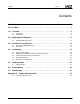
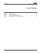
Memory Map 32430C 7 7.0Memory Map Figures 7-1, 7-2, and 7-3 show the system memory. Figure 7-1 is the GLIU Descriptor Map, Figure 7-2 shows the Core Cache descriptors, and Figure 7-3 on page 32 shows the Core cache region configurations. Figure 7-4 on page 33 shows the flow of GeodeROM in the GX processor/CS5535 system. Memory Descriptors BM - Base Mask BMO - Base Mask Offset R - Range RO - Range Offset SC - Swiss Cheese No Swiss Cheese Offset Figure 7-1.
430C Memory Map RCONF_DEFAULT ROMRC RCONF_DEFAULT ROMBASE ROM FFFC0000h PCI Memory Mapped PCI PCI PCI Memory Mapped Frame Buffer 50000000h Memory Mapped Video Registers Memory Mapped VSA RCONF_DEFAULT DEVRG PCI Frame Buffer RCONF_SMM RCONF_DEFAULT SYSTOP VSA 40400000h subtracted from Extended Memory Top of DRAM VSA and Frame Buffer PCI RCONF_DEFAULT SYSRC Extended Memory Top of System (OS) RAM RCONF_A0_BF-RCONF_E0_FF RCONF_DEFAULT SYSRC System and Option ROMs Conventional Memory RCONF_BYPA
32430C Memory Map Reset ROM Fetch CPU ID Correct? Uses CPU ID instruction. N Halt Y N CMOS/NVRAM Valid and Checksum Ok? Y Y Load CMOS/ NVRAM Defaults Failed to Boot 3 Times? Failed boots need a POR reset and will always take this path. N Early CS5535 Initialization PLL Flag indicates 2nd Pass? Y N Jumper settings correspond to a table of SKUs for each revision of the CPU. PLL settings can be set manually for debug.
32430C Memory Map Finish Post CS5535 descriptor set here, after shadow.
Appendix A: Support Documentation 32430C A Appendix ASupport Documentation A.1 Document Revision History This section reports the revision/creation process of the porting guide. Any revisions (i.e., additions, deletions, parameter corrections, etc.) are recorded in the table(s) below. Table A-1. Revision History Revision # (PDF Date) Revisions / Comments A (30-Jun-2005) Initial release. B (22-Mar-2006) The goal was to remove “Confidential” to make this an non-NDA document.
www.amd.com One AMD Place • P.O.