AR-B1631ET User’s Guide ACROSSER® AR-B1631ET (Extended Temperature) powered by AMD Geode LX800, EPIC SBC with CRT, LCD, LAN, USB2.0, PCI/104 User’s Guide Edition: 1.
AR-B1631ET User’s Guide Contents 1 INTRODUCTION ............................................. 4 2 SYSTEM SETUP ............................................... 7 2.1 AR-B1631ET OVERVIEW........................................................... 7 2.2 SYSTEM SETTINGS................................................................... 8 2.2.1 2.2.2 2.2.3 2.2.4 2.2.5 2.2.6 2.2.7 2.2.8 2.2.9 2.2.10 2.2.11 2.2.12 2.2.13 2.2.14 2.2.15 2.2.16 2.2.17 2.2.18 2.2.19 2.2.20 2.2.21 2.2.22 2.2.22 JP5 (SERIRQ) ..........
AR-B1631ET User’s Guide 4.5 PERIPHERALS ......................................................................... 19 4.6 BOOT................................................................................... 21 4.7 BIOS EXIT ............................................................................. 22 5 I/O ADDRESS, IRQ AND MEMORY MAPPING .23 5.1 I/O ADDRESS MAPPING ........................................................ 23 5.2 IRQ MAPPING..............................................................
AR-B1631ET User’s Guide 1 INTRODUCTION Welcome to the AR-B1631ET Single Board Computer, the AR-B1631ET low power AMD Geode LX800 processor board with the advanced chipset CS5536 (CS5535). The board is designed for extreme environments, it can be operated from -40°C to +75°C which can make a lot of outdoor applications available, such as Traffic Control, Vehicle Computer, Remote Workstation, Outdoor Data Acquisition, Aviation or Military industries.
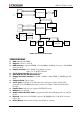
AR-B1631ET User’s Guide CRT MEMORY BUS LX Processor TFT lvds (24Bit) SODIMM200 DDR CRT OUT TO ETX CON PCI BUS(33MHz or 66MHz) IDE AND CF CARD 10/100M Ethernet PRIMARY IDE ATA-66 South Bridge (CS5535/CS5536) USB2.0 AC97 CODEC USB x 2 PCI(33/66 MHz) 14.
AR-B1631ET User’s Guide Power Req.: +5V 2A and +12V 1A maximum PC Board: 6 layers, EMI considered GPIO: 8pin (4 output and 4 input) TTL compatible PCB Dimensions: 6.5” x 4.
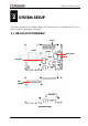
AR-B1631ET User’s Guide 2 SYSTEM SETUP This chapter describes how to install the AR-B1631ET. At first, the layout of the AR-B1631ET is shown, and the unpacking information is described. 2.
AR-B1631ET User’s Guide CN8 JP5 LPT1 J2 DIO1 AUDIO1 CDIN1 COM2 JP1 JRS1 JP6 CN10 COM4 JP4 CN4 COM3 CN9 J5 IR1 J3 USB_A2 USB_A1 2.2 SYSTEM SETTINGS Jumper pins allow you to set specific system parameters. Set them by changing the pin location of the jumper blocks. (A jumper block is a small plastic-encased conductor that slips over the pins.) To change a jumper setting, remove the jumper from its current location with your fingers or small needle-nosed pliers.
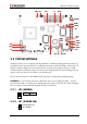
AR-B1631ET User’s Guide 2.2.3 DIO1 (GPIO) 1 2 9 10 2.2.4 GND XOUT0 XOUT2 XIN0 XIN2 2 4 6 8 10 +5V XOUT1 XOUT3 XIN1 XIN3 AUDIO1 (AUDIO) 1 2 9 2.2.5 10 1 3 5 7 9 LINE OUT R GND LINE IN R MIC IN GND 2 4 6 8 10 LINE OUT L GND LINE IN L GND GND COM2, COM3, COM4 (RS232) 1 2 9 2.2.
AR-B1631ET User’s Guide 2.2.7 IR1 1 2 3 4 5 1 5 2.2.8 5V NC IRRX GND IRTX J3 (CLEAR CMOS) 1 1-2 2-3 3 2.2.9 NORMAL CLEAR CMOS CN10 (LCD SETTING) 1 2 5 1-3 3-5 2-4 4-6 6 -SHFCLK SHFCLK 3.3V LCD 5V LCD 2.2.10 CDIN1 (CDIN) 1 1 2 3 4 4 CD_L GND GND CD_R 2.2.11 CN9 (POWER) 1 2 2 +12V GND 1 2.2.
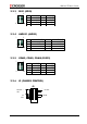
AR-B1631ET User’s Guide 2.2.13 J5 (LCD BACKLIGHT) 1 2 3 4 5 6 1 5 +12V +12V GND BLT GND NC 2.2.14 JP4 (LCD LVDS) 2 1 30 2 4 6 8 10 12 14 16 18 20 22 24 26 28 30 29 GND NC NC GND NC NC NC LVDS_TXC+ GND LVDS_TX2LVDS_TX1+ NC LVDS_TX0LVDS_TX3POWER 1 3 5 7 9 11 13 15 17 19 21 23 25 27 29 POWER NC GND NC NC NC NC GND LVDS_TXCLVDS_TX2+ NC LVDS_TX1LVDS_TX0+ LVDS_TX3+ POWER 2.2.
AR-B1631ET User’s Guide 2.2.16 BUZZER EXTERNAL 2.2.17 J4 (PC104+) A1 B1 C1 D1 1 2 3 4 5 6 7 8 9 10 11 12 13 14 15 16 17 18 19 20 21 22 23 24 25 26 27 28 29 30 A NC NC AD5 C/BE0# GND AD11 AD14 +3.3V SERR# GND STOP# +3.3V FRAME# GND AD18 AD21 +3.3V IDSEL0 AD24 GND AD29 +5V REQ0# GND GNT1# +5V CLK GND +12V NC B SERIRQ AD2 GND AD7 AD9 NC AD13 C/BE1# GND PERR# +3.3V TRDY# GND AD16 +3.3V AD20 AD23 GND C/BE3# AD26 +5V AD30 GND REQ2# NC CLK +5V INTD# INTA# NC C +5V AD1 AD4 GND AD8 AD10 GND AD15 PULL UP +3.
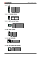
AR-B1631ET User’s Guide 2.2.18 JP6 (IDE Cable Select, NOTE 2) Open Close ATA33 ATA66 above 2.2.19 USBA_1 & USBA_2 (NOTE 2) 1 2 9 10 1 2 3 4 5 6 7 8 9 10 5V 5V USB1USB2USB1+ USB2+ GND GND GND GND 2.2.20 USB1 & USB2 (NOTE 2) 1 2 3 4 5 6 7 8 5V USBUSB+ GND 5V USBUSB+ GND 2.2.
AR-B1631ET User’s Guide 2.2.22 CN4 (RS422 & RS485) 1 4 1 2 3 4 RS422TX+/RS485TRX+ RS422TX-/RS485TRXRS422RX+ RS422RX- 2.2.22 CF1 (NOTE 1) NOTE 1: For using both Hard Disk and Compact Flash, you have to use the ATA33 IDE cable. IF you want to use the ATA66/100 mode with the Hard Disk, you must put the jumper on JP6 and use the special IDE cable. The cable is like below: IDE HOST Usually the ATA66/100 cable at Pin 34 at host side is defined as CABLE ID and connected to ground.
AR-B1631ET User’s Guide 3 LCD FLAT PANEL DISPLAY This chapter describes the configuration and installation procedures for LCD displays. LVDS1 LCD Panel AR-B1631ET Backlight connect to J5 Inverter Backlight Power LCD Panel Block Diagram Please visit our web site or contact our technical support department for supports of LCD connecting.
AR-B1631ET User’s Guide 4 BIOS CONSOLE This chapter describes the AR-B1631ET BIOS menu displays and explains how to perform common tasks needed to get up and running, and presents detailed explanations of the elements found in each of the BIOS menus. The following topics are covered: BIOS Setup Overview Advanced CMOS Setup Peripheral Setup Boot BIOS Exit 4.
AR-B1631ET User’s Guide The option allows you to view some basic system hardware configuration and to set the system clock as well as error handling. If the CPU board is already installed in a working system, you do not need to select this option anymore. Date & Time Setup Highlight the field and then press the [Page Up] / [Page Down] or [+]/[-] keys to set the current date. Follow the month, day and year format.
AR-B1631ET User’s Guide Video Memory Size [8M] Configuration options: [None] [8M] [16M] [32M] [64M] [128M] [254M] Output Display [CRT] This allows you to choose the output of your system display. Configuration options: [CRT] [Flat Panel] [Panel +CRT] Flat Panel Type [Auto] This allows you to choose the flat panel type Configuration options: [Auto] [LVDS] [TFT] Resolution [800x600] This allows you to choose the display resolution. Refresh Rate [60Hz] This allows you to choose the display Refresh Rate.
AR-B1631ET User’s Guide 4.4 PnP/PCI PnP/PCI Reset Configuration Data [Disable] Normally, you leave this field Disabled. Select Enabled to reset the Extended System Configuration Data (ESCD) when you exit the Setup if you have installed a new add-on and the system reconfiguration has caused such a serious conflict that the operating system cannot boot. Resources Controlled By [Auto (ESCD)] This field sets control over the IRQ resources by the automatic (ESCD) system or manual assignment of IRQ channels.
AR-B1631ET User’s Guide Onboard Serial Port 1 [3F8/IRQ4] Choose the serial port 1 I/O address. Do not set port 1, 2, 3 and 4 to the same address except for Disabled or Auto. Onboard Serial Port 2 [2F8/IRQ3] Choose the serial port 2 I/O address. Do not set port 1, 2, 3 and 4 to the same address except for Disabled or Auto. Onboard Serial Port 3 [3E8/IRQ11] Choose the serial port 3 I/O address. Do not set port 1, 2, 3 and 4 to the same address except for Disabled or Auto.
AR-B1631ET User’s Guide OnChip IDE Device With this option you can enable or disable your IDE channel and set the PIO mode or UDMA mode. 4.6 BOOT BOOT First/Second/Third Boot Device HDD-0 SCSI CDROM HDD-1 USB-FDD USB-ZIP USB-CDROM USB-HDD LAN Disabled Boot Other Device [Enabled] Configuration options: [Enabled] [Disabled]. LAN Boot Select [Disabled] This allows you to enable or disable the LAN Boot function.
AR-B1631ET User’s Guide 4.7 BIOS EXIT Exit When you have made all of your selections from the various menus in the Setup program, save your changes and exit Setup. Select Exit from the menu bar to display the following menu. Save & Exit Setup Typing “Y” will quit the Setup Utility and save the user setup value to RTC CMOS. Type “N” will return to Setup Utility. Load Optimized Defaults Selecting this field loads the factory defaults for BIOS and Chipset Features that the System automatically detects.
AR-B1631ET User’s Guide 5 I/O ADDRESS, IRQ AND MEMORY MAPPING 5.
AR-B1631ET User’s Guide 5.2 IRQ MAPPING 5.
AR-B1631ET User’s Guide 6 GPIO SAMPLE CODE /*[]=====================================================================[]*/ /*|| GPIO Test utility for W83627HF. ||*/ /*|| Date : 10/18/2005 ||*/ /*|| Author : Willy ||*/ /*[]=====================================================================[]*/ /*[]=====================================================================[]*/ /*|| Include files ||*/ /*[]=====================================================================[]*/ #include #include
AR-B1631ET User’s Guide /////// Input High Test /////////////////////////////////////////////////// printf("\nConnect GPI Pins to High ? [Y/N] .......
AR-B1631ET User’s Guide Show_Byte=Show_Byte|0x04; else if(Read_Byte&0x08) //GPI13 Show_Byte=Show_Byte|0x08; else if(Read_Byte&0x10) //GPI14 Show_Byte=Show_Byte|0x10; else if(Read_Byte&0x20) //GPI15 Show_Byte=Show_Byte|0x20; else if(Read_Byte&0x40) //GPI16 Show_Byte=Show_Byte|0x40; else if(Read_Byte&0x80) //GPI17 Show_Byte=Show_Byte|0x80; else Show_Byte=Show_Byte&0xFB; Show_Byte=Show_Byte&0xF7; Show_Byte=Show_Byte&0xEF; Show_Byte=Show_Byte&0xDF; Show_Byte=Show_Byte&0xBF; Show_Byte=Show_Byte&0x7F; if(Show_B
AR-B1631ET User’s Guide // Set W83627HF GPIO10~17 to Low outportb(IO_PORT_BASE,0xF1); outportb(IO_PORT_BASE+1,0x00); printf("\nGPO Pins is Low ? [Y/N] ............
AR-B1631ET User’s Guide return(0); } /*[]=====================================================================[]*/ /*|| Function : Show_Title() ||*/ /*|| Input : ||*/ /*|| Change : ||*/ /*|| Return :||*/ /*|| Description: Show Title string. ||*/ /*[]=====================================================================[]*/ void Show_Title() { clrscr(); printf("GPIO Control test for W83627HF\n"); printf("1. GPIO.EXE I ==--> Test GPI.\n"); printf("2. GPIO.EXE O ==--> Test GPO.
AR-B1631ET User’s Guide void Enter_Config(BYTE IO_PORT_BASE) { outportb(IO_PORT_BASE,0x87); outportb(IO_PORT_BASE,0x87); } /*[]=====================================================================[]*/ /*|| Function : Exit_Config() ||*/ /*|| Input : BYTE IO_PORT_BASE ||*/ /*|| Change : ||*/ /*|| Return :||*/ /*|| Description: Exit chip configuration key.