GA-7VASFS-FS AMD Socket A Processor Motherboard USER'S MANUAL Pentium®4 Processor Motherboard Rev.
English Table of Content Item Checklist .......................................................................................... 4 Chapter 1 Introduction ............................................................................. 5 Features Summary ....................................................................................... 5 GA-7VASFS-FS Motherboard Layout ........................................................... 7 Block Diagram ............................................................
PC Health Status ........................................................................................ 45 Frequency/Voltage Control ......................................................................... 46 Load Fail-Safe Defaults .............................................................................. 47 Load Optimized Defaults ............................................................................ 48 Set Supervisor/User Password .............................................................
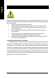
English Computer motherboards and expansion cards contain very delicate Integrated Circuit (IC) chips. To protect them against damage from static electricity, you should follow some precautions whenever you work on your computer. 1. Unplug your computer when working on the inside. 2. Use a grounded wrist strap before handling computer components. If you do not have one, touch both of your hands to a safely grounded object or to a metal object, such as the power supply case. 3.
Features Summary Form Factor CPU Chipset Memory I/O Control Slots On-Board IDE On-Board Peripherals y 30.4cm x 24.4cm ATX size form factor, 4 layers PCB. y Socket A processor AMD AthlonTM/AthlonTM XP/ DuronTM (K7) 128K L1 & 256K/64K L2 cache on die 266/333/400 MHz FSB and DDR bus speeds y Supports 1.
English Hardware Monitor y y y y CPU/Power/System Fan Revolution detect CPU/Power/System Fan Fail Warning CPU Overheat Warning System Voltage Detect On-Board Sound y Realtek ALC655 CODEC y Line Out / 2 front speaker y Line In / 2 rear speaker(by s/w switch) y Mic In / center& subwoofer(by s/w switch) On-Board LAN y AUX_In y Build in RTL8101L Chipset On-Board IEEE1394 PS/2 Connector y VT6307 y PS/2 Keyboard interface and PS/2 Mouse interface BIOS y Licensed AWARD BIOS y Supports Q-Flash Additiona
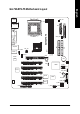
English GA-7VASFS-FS Motherboard Layout KB_MS RAM_LED CPU_FAN FDD USB_1394 ATX GA-7VASFS-FS COMA SOCKET A PWR_FAN ATX_12V AUX_IN AGP DDR2 KT600 DDR3 AUDIO DDR1 F_AUDIO IDE1 USB_LAN IDE2 LPT SPDIF CODCE BAT PCI1 SW1 S_ATA1 VT8237 S_IRQ CI RTL8101L S_ATA0 CLR_CMOS PCI2 BZ PCI3 IT8705 VT6307 SYS_FAN PCI4 PWR_LED FS BIOS F_USB2 PCI5 CNR -7- F_1394 F_PANEL F_USB1 Introduction
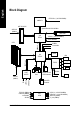
CPUCLK+/- (100/133/166MHz) AMD-K7TM AGP 2X/4X/8X System Bus100/133/166 MHz AGPCLK (66MHz) DDR RAM VIA KT600 66MHz V_Link 5 PCI HCLK+/- (100/133/166MHz) AGPCLK66MHz 33 MHz 14.318 MHz 48 MHz BIOS VIA VT8237 1394 AC97 Link Floppy IT8705 LPT Port PS/2 KB/Mouse ATA66/100/133 IDE Channels 8 USB Ports 24 MHz 33 MHz COM Port PCICLK (33MHz) USBCLK (48MHz) 14.
English -9- Introduction
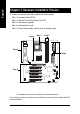
To set up your computer, you must complete the following steps: Step 1- Set system Switch (SW1) Step 2- Install the Central Processing Unit (CPU) Step 3- Install memory modules Step 4- Install expansion cards Step 5- Connect ribbon cables, cabinet wires, and power supply Step 4 Step 1 Step 2 Step 4 Step 4 Step 3 FS English Chapter 2 Hardware Installation Process Congratulations you have accomplished the hardware installation! Turn on the power supply or connect the power cable to the power outlet.
Step1-1: CPU Speed Setup The system bus frequency can be switched at 100/133/166/200MHz by adjusting system switch FS (SW1). (The internal frequency depend on CPU.) O: ON / X :OFF 1 SW1 Default Setting: 100MHz ON SW1 CPU CLOCK 1 100MHz ON 100MHz : Fix FSB 200MHz CPU Auto : Support FSB 266/333/400 MHz CPU You must set SW1 to 100MHz when Auto OFF you used FSB 200MHz CPU.
English Step1-2: CPU Installation Before installing the processor, adhere to the following warning: 1.Please make sure the CPU type is supported by the motherboard. 2.If you do not match the CPU socket Pin 1 and CPU cut edge well, it will cause improper installation. Please change the insert orientation. CPU Top View CPU Bottom View Socket Actuation Lever Pin1 indicator 2. Locate Pin 1 in the socket and look for a (golden) cut edge on the CPU 1. Pull up the CPU socket lever and up to 90-degree angle.
Before installing the CPU Heat Sink , adhere to the following warning: 1. Please use AMD approved cooling fan. 2. We recommend you to apply the thermal paste to provide better heat conduction between your CPU and Cooling Fan. 3. Make sure the CPU fan power cable is plugged in to the CPU fan connector, this completes the installation. Please refer to CPU cooling fan user's manual for more detail installation procedure. 2. Use qualified fan approved by AMD. 1.
Before installing the memory modules, adhere to the following warning: 1. When RAM_LED is ON, do not install / remove DIMM from socket. 2. Please note that the DIMM module can only fit in one direction due to the one notch. Wrong orientation will cause improper installation. Please change the insert orientation. The motherboard has 3 dual inline memory module(DIMM) sockets. The BIOS will automatically detects memory type and size. To install the memory module, just push it vertically into the DIMM Slot.
English 1. The DIMM slot has a notch, so the DIMM memory module can only fit in one direction. 2. Insert the DIMM memory module vertically into the DIMM slot. Then push it down. 3. Close the plastic clip at both edges of the DIMM slots to lock the DIMM module. Reverse the installation steps when you wish to remove the DIMM module.
English Step 3: Install expansion cards 1. Read the related expansion card's instruction document before install the expansion card into the computer. 2. Remove your computer's chassis cover, necessary screws and slot bracket from the computer. 3. Press the expansion card firmly into expansion slot in motherboard. 4. Be sure the metal contacts on the card are indeed seated in the slot. 5. Replace the screw to secure the slot bracket of the expansion card. 6. Replace your computer's chassis cover. 7.
Step 4-1: I/O Back Panel Introduction X Z Y \ [ X PS/2 Keyboard and PS/2 Mouse Connector PS/2 Mouse Connector (6 pin Female) ¾This connector supports standard PS/2 keyboard and PS/2 mouse. PS/2 Keyboard Connector (6 pin Female) YIEEE 1394 and USB Connector ¾This connector supports IEEE 1394 and USB devices. 1394 USB 0 USB 1 ZParallel Port, Serial Port and SPDIF Port (LPT/COMA/SPDIF) Parallel Port (25 pin Female) ¾ This connector supports 1 standard COM port, 1 Parallel port and 1 SPDIF port.
English [ USB & LAN Connector ¾ Before you connect your device(s) into USB connector(s), please make sure your device(s) such as USB keyboard,mouse, scanner, zip, speaker..etc. Have a standard USB interface. LAN Also make sure your OS supports USB controller. USB 0 If your OS does not support USB controller, please contact OS vendor for possible patch USB 1 or driver upgrade. For more information please contact your OS or device(s) vendors.
1 3 English Step 4-2: Connectors & Jumper Setting Introduction 9 2 7 5 6 13 14 12 17 8 18 19 4 FS 11 10 16 1) ATX_12V 2) ATX 3) CPU_FAN 4) SYS_FAN 5) PWR_FAN 6) IDE1/IDE2 7) FDD 8) S_ATA0/S_ATA1 9) RAM_LED 10) PWR_LED 11) F_PANEL 15 12) BAT 13) F_AUDIO 14) AUX_IN 15) F_USB1/F_USB2 16) F_1394 17) S_IRQ 18) CI 19) CLR_CMOS - 19 - Hardware Installation Process
This connector (ATX _12V) suppliesthe CPU operation voltage (Vcore). If this " ATX_ 12V connector" is not connected, system cannot boot. 4 1 2 Pin No. 1 2 3 4 Definition GND GND +12V +12V FS 3 2) ATX (ATX Power) AC power cord should only be connected to your power supply unit after ATX power cable and other related devices are firmly connected to the mainboard. 10 1 FS English 1) ATX_12V (+12V Power Connector) GA-7VASFS-FS Motherboard - 20 - 20 11 Pin No.
Please note, a proper installation of the CPU cooler is essential to prevent the CPU from running under abnormal condition or damaged by overheating.The CPU fan connector supports Max. current up to 600 mA. Definition GND +12V Sense FS 1 Pin No. 1 2 3 4) SYS_FAN (System FAN Connector) This connector allows you to link with the cooling fan on the system case to lower the system temperature. Definition GND +12V Sense FS 1 Pin No.
This connector allows you to link with the cooling fan on the system case to lower the system temperature. Pin No. 1 2 3 FS 1 Definition GND +12V Sense 6) IDE1/ IDE2 (IDE1/IDE2 Connector) Please connect first harddisk to IDE1 and connect CDROM to IDE2. The red stripe of the ribbon cable must be the same side with the Pin1.
Please connect the floppy drive ribbon cables to FDD. It supports 360K,720K,1.2M,1.44M and 2.88Mbytes floppy disk types. The red stripe of the ribbon cable must be the same side with the Pin1. 34 1 FS 2 33 8) S_ATA0/S_ATA1 (Serial ATA Connector) You can connect the Serial ATA device to this connector, it provides you high speed transfer rates (150MB/sec).If you wish to use SATA0 and SATA1, please Enable " OnChip Serial ATA " item. Then, install the correct driver to have proper operation.
Do not remove memory modules while DIMM LED is on. It might cause short or other unexpected damages due to the 2.5V stand by voltage. Remove memory modules only when AC Power cord is disconnected. + FS - 10) PWR_LED PWR_LED is connect with the system power indicator to indicate whether the system is on/off. It will blink when the system enters suspend mode. If you use dual color LED, power LED will turn to another color. 1 FS English 9) RAM_LED GA-7VASFS-FS Motherboard - 24 - Pin No.
Please connect the power LED, PC peaker, reset switch and power switch etc of your chassis front panel to the F_PANEL connector according to the pin assignment above.
+ CAUTION FS Danger of explosion if battery is incorrectly replaced. Replace only with the same or equivalent type recommended by the manufacturer. Dispose of used batteries according to the manufacturer's instructions. If you want to erase CMOS... 1.Turn OFF the computer and unplug the power cord. 2.Remove the battery, wait for 30 second. 3.Re-install the battery. 4.Plug the power cord and turn ON the computer.
English 14) AUX_IN (AUX In Connector) Connect other device(such as PCI TV Tunner audio out)to the connector. Pin No. 1 2 3 4 FS 1 Definition AUX-L GND GND AUX_R 15) F_ USB1 / F_USB2 (Front USB Connector, Yellow) Be careful with the polarity of the front USB connector. Check the pin assignment while you connect the front USB cable. Please contact your nearest dealer for optional front USB cable. Be careful with the polarity of the F_USB connector.
Please Note: Serial interface standard set by Institute of Electrical and Electronics Engineers, which has features like high speed, high bandwidth and hot plug. 10 1 9 Definition NDCDBNSINB NSOUTB NDTRBGND NDSRBNRTSBNCTSBNRIBNo Pin FS 2 Pin No. 1 2 3 4 5 6 7 8 9 10 17) S_IRQ (Serial IRQ Connector) This connector is for special design, for example: PCMCIA add on card. 1 FS English 16) F_1394 (IEEE 1394 Connector) GA-7VASFS-FS Motherboard - 28 - Pin No.
This 2 pin connector allows your system to enable or disable the "case open" item in BIOS if the system case begin remove. Pin No. Definition 1 Signal 2 GND FS 1 19) CLR_CMOS (Clear CMOS jumper) You may clear the CMOS data to its default values by this jumper. Default doesn’t include the "Shunter" to prevent from improper use this jumper. To Clear CMOS, temporarily short 1-2 pin.
English GA-7VASFS-FS Motherboard - 30 -
BIOS Setup is an overview of the BIOS Setup Program. The program that allows users to modify the basic system configuration. This type of information is stored in battery-backed CMOS RAM so that it retains the Setup information when the power is turned off. ENTERING SETUP Powering ON the computer and pressing immediately will allow you to enter Setup. If you require more advanced BIOS settings, please go to "Advanced BIOS" setting menu.
English GETTING HELP Main Menu The on-line description of the highlighted setup function is displayed at the bottom of the screen. Status Page Setup Menu / Option Page Setup Menu Press F1 to pop up a small help window that describes the appropriate keys to use and the possible selections for the highlighted item. To exit the Help Window press . The Main Menu (For example: BIOS Ver. : D5) Once you enter Award BIOS CMOS Setup Utility, the Main Menu (Figure 1) will appear on the screen.
Integrated Peripherals English z This setup page includes all onboard peripherals. z Power Management Setup This setup page includes all the items of Green function features. z PnP/PCI Configurations This setup page includes all the configurations of PCI & PnP ISA resources. z PC Health Status This setup page is the System auto detect Temperature, voltage, fan, speed. z Frequency/Voltage Control This setup page is control CPU's clock and frequency ratio.
English Standard CMOS Features CMOS Setup Utility-Copyright (C) 1984-2003 Award Software Standard CMOS Features Date (mm:dd:yy) Tue, Aug 13 2002 Item Help Time (hh:mm:ss) 22:31:24 Menu Level Change the day, month, IDE Primary Master [None] IDE Primary Slave [None] year IDE Secondary Master [None] IDE Secondary Slave [None] Sun. to Sat. Acoustic Management [Disabled] Drive A [1.44M, 3.5 in.] Drive B [None] Jan. to Dec.
The category identifies the types of hard disk from drive C to F that has been installed in the computer. There are two types: auto type, and manual type. Manual type is user-definable; Auto type which will automatically detect HDD type. Note that the specifications of your drive must match with the drive table. The hard disk will not work properly if you enter improper information for this category. If you select User Type, related information will be asked to enter to the following items.
English None No floppy drive installed 360K, 5.25 in. 5.25 inch PC-type standard drive; 360K byte capacity. 1.2M, 5.25 in. 5.25 inch AT-type high-density drive; 1.2M byte capacity (3.5 inch when 3 Mode is Enabled). 720K, 3.5 in. 3.5 inch double-sided drive; 720K byte capacity 1.44M, 3.5 in. 3.5 inch double-sided drive; 1.44M byte capacity. 2.88M, 3.5 in. 3.5 inch double-sided drive; 2.88M byte capacity. Floppy 3 Mode Support (for Japan Area) Disabled Normal Floppy Drive.
The POST of the BIOS will determine the amount of base (or conventional) memory installed in the system. The value of the base memory is typically 512 K for systems with 512 K memory installed on the motherboard, or 640 K for systems with 640 K or more memory installed on the motherboard. Extended Memory The BIOS determines how much extended memory is present during the POST. This is the amount of memory located above 1 MB in the CPU's memory address map.
English First / Second / Third Boot Device Floppy Select your boot device priority by Floppy. LS120 Select your boot device priority by LS120. HDD-0~3 Select your boot device priority by HDD-0~3. SCSI Select your boot device priority by SCSI. CDROM Select your boot device priority by CDROM. ZIP Select your boot device priority by ZIP. USB-FDD Select your boot device priority by USB-FDD. USB-ZIP Select your boot device priority by USB-ZIP.
English Integrated Peripherals CMOS Setup Utility-Copyright (C) 1984-2003 Award Software Integrated Peripherals OnChip IDE Channel0 [Enabled] Item Help OnChip IDE Channel1 [Enabled] Menu Level OnChip Serial ATA [Enabled] If a hard disk AC97 Audio [Auto] controller card is MC97 Modem [Auto] used, set at Disabled USB 1.1 Controller [Enabled] USB 2.
English OnChip Serial ATA Disabled Disable VT8237 Serial ATA. Enabled Enable VT8237 Serial ATA support. (Default Value) AC97 Audio Auto Enable onboard AC'97 audio function. (Default Value) Disabled Disable this function. MC97 Modem Auto Enable onboard MC97 controller. (Default Value) Disabled Disable this function. USB 1.1 Controller Disable this function if you are not using onboard USB 1.1 feature. Enabled Enable USB 1.1 Controller. (Default value) Disabled Disable USB 1.1 Controller.
Enabled Enable USB Mouse Support.(Default value) Disabled Disable USB Mouse Support. English USB Mouse Support Onboard H/W LAN Enabled Enable Onboard H/W LAN function. (Default value) Disabled Disable this function. Onboard H/W 1394 Enabled Enable onboard IEEE 1394 function.(Default value) Disabled Disable this function. Onboard Serial Port 1 Auto BIOS will automatically setup the port 1 address. 3F8/IRQ4 Enable onboard Serial port 1 and address is 3F8.
English Power Management Setup CMOS Setup Utility-Copyright (C) 1984-2003 Award Software Power Management Setup ACPI Suspend Type [S3(STR)] Item Help USB Device Wake-Up From S3 [Disabled] Menu Level Soft-Off by PWRBTN [Instant-Off] [S1] AC BACK Function [Memory] Set suspend type to Keyboard Power On Mouse Power On [Disabled] [Disabled] Power On Suspend under ACPI OS PME Event Wake Up [Disabled] Modem Ring Resume [Disabled] [S3] Resume by Alarm [Disabled] Set suspend type to x Date (o
Memory System power on depends on the status before AC lost. (Default value) Soft-Off Always in Off state when AC back. Full-On Always power on the system when AC back. Keyboard Power On Password Enter from 1 to 8 characters to set the Keyboard Power On Password. Disabled Disabled this function. (Default value) Keyboard 98 If your keyboard have "POWER Key" button, you can press the key to power on your system. Mouse Power On Disabled Disabled this function.
English PnP/PCI Configurations CMOS Setup Utility-Copyright (C) 1984-2003 Award Software PnP/PCI Configurations PNP OS Installed [Yes] Item Help PCI 1/PCI 5 IRQ Assignment [Auto] Menu Level PCI 2 IRQ Assignment [Auto] Select Yes if you are PCI 3 IRQ Assignment [Auto] using a Plug and Play PCI 4 IRQ Assignment [Auto] capable operating system Select No if you need the BIOS to configure non-boot devices : Move Enter:Select +/-/PU/PD:Value F5:Previous Values F10:Save ESC:Exit F6:Fail-Safe
English PC Health Status CMOS Setup Utility-Copyright (C) 1984-2003 Award Software PC Health Status Vcore 1.74V Item Help +3.3V 3.28V Menu Level +5V 5.107V +12V 11.668V 5VSB 4.
English Frequency/Voltage Control CMOS Setup Utility-Copyright (C) 1984-2003 Award Software Frequency/Voltage Control DRAM Clock (MHz) [Auto] Item Help Menu Level : Move Enter:Select +/-/PU/PD:Value F5:Previous Values F10:Save ESC:Exit F6:Fail-Safe Defaults F1:General Help F7:Optimized Defaults Figure 8: Frequency/Voltage Control DRAM Clock (MHz) Please set DRAM Clock according to your requirement. If you use DDR266 DRAM module, please set "DRAM Clock(MHz)" to Auto or 266.
English Load Fail-Safe Defaults CMOS Setup Utility-Copyright (C) 1984-2003 Award Software Standard CMOS Features Load Fail-Safe Defaults Advanced BIOS Features Load Optimized Defaults Integrated Peripherals Set Supervisor Password Power Management Setup Set User Password PnP/PCI Configurations Save & Exit Setup PC Health Status Load Fail-Safe Defaults? Exit(Y/N)?Y Without Saving Frequency/Voltage Control ESC:Quit F8: Q-Flash :Select Item F10:Save & Exit Setup Load Fail-Safe Defaults Figure 9:
English Load Optimized Defaults CMOS Setup Utility-Copyright (C) 1984-2003 Award Software Standard CMOS Features Load Fail-Safe Defaults Advanced BIOS Features Load Optimized Defaults Integrated Peripherals Set Supervisor Password Power Management Setup Set User Password PnP/PCI Configurations Save & Exit Setup PC Health Status Exit Without Saving Load Optimized Defaults? (Y/N)?Y Frequency/Voltage Control ESC:Quit :Select Item F8: Q-Flash F10:Save & Exit Setup Load Optimized Defaults Figure
English Set Supervisor/User Password CMOS Setup Utility-Copyright (C) 1984-2003 Award Software Standard CMOS Features Load Fail-Safe Defaults Advanced BIOS Features Load Optimized Defaults Integrated Peripherals Set Supervisor Password Power Management Setup Set User Password PnP/PCI Configurations Save & Exit Setup PC Health Status Exit Without Saving Enter Password: Frequency/Voltage Control ESC:Quit F8: Q-Flash :Select Item F10:Save & Exit Setup Change/Set/Disable Password Figure 11: Passw
English Save & Exit Setup CMOS Setup Utility-Copyright (C) 1984-2003 Award Software Standard CMOS Features Load Fail-Safe Defaults Advanced BIOS Features Load Optimized Defaults Integrated Peripherals Set Supervisor Password Power Management Setup Set User Password PnP/PCI Configurations & Exit Save to CMOS and EXITSave (Y/N)? Y Setup PC Health Status Exit Without Saving Frequency/Voltage Control ESC:Quit :Select Item F8: Q-Flash F10:Save & Exit Setup Save Data to CMOS Figure 12: Save & Exit S
English Exit Without Saving CMOS Setup Utility-Copyright (C) 1984-2003 Award Software Standard CMOS Features Load Fail-Safe Defaults Advanced BIOS Features Load Optimized Defaults Integrated Peripherals Set Supervisor Password Power Management Setup Set User Password PnP/PCI Configurations Save & Exit Setup PC Health Status Exit Without Saving Quit Without Saving (Y/N)? N Frequency/Voltage Control ESC:Quit F8: Q-Flash :Select Item F10:Save & Exit Setup Abandon all Data Figure 13: Exit Without
English GA-7VASFS-FS Motherboard - 52 -